

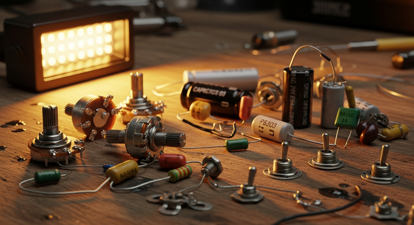
4-Conductor Humbucker in Series: Basic Schematic
If you are looking for a humbucker series wiring Clear and practical, you're in the right place. Here you'll find the diagram, explanations of the connections, and tips for avoiding common mistakes.
Introduction
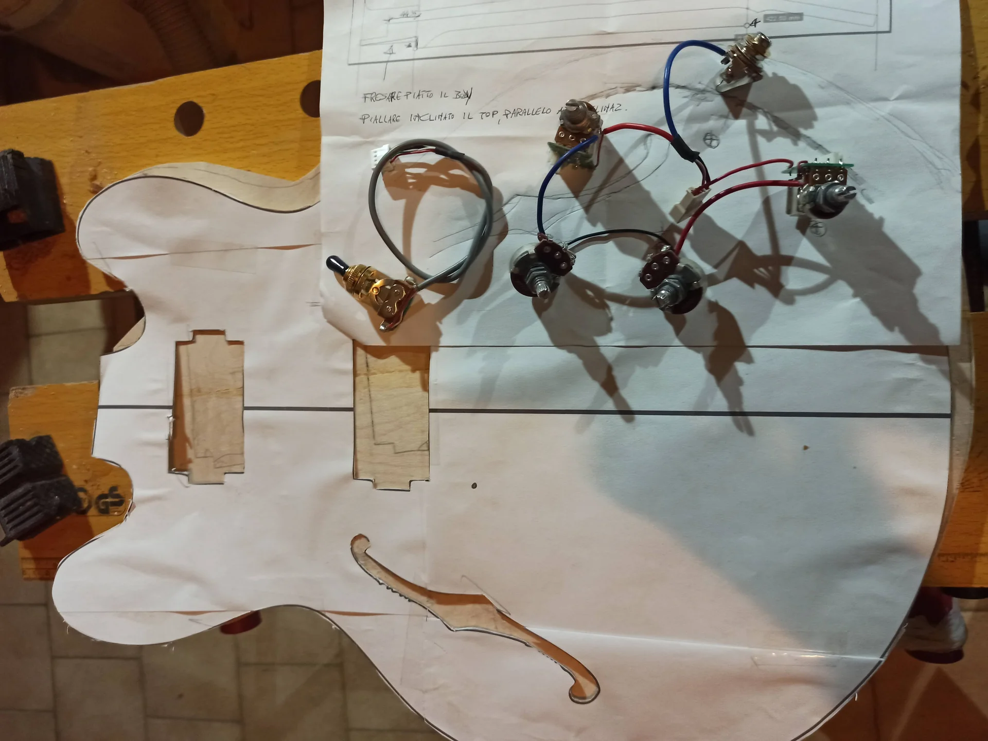
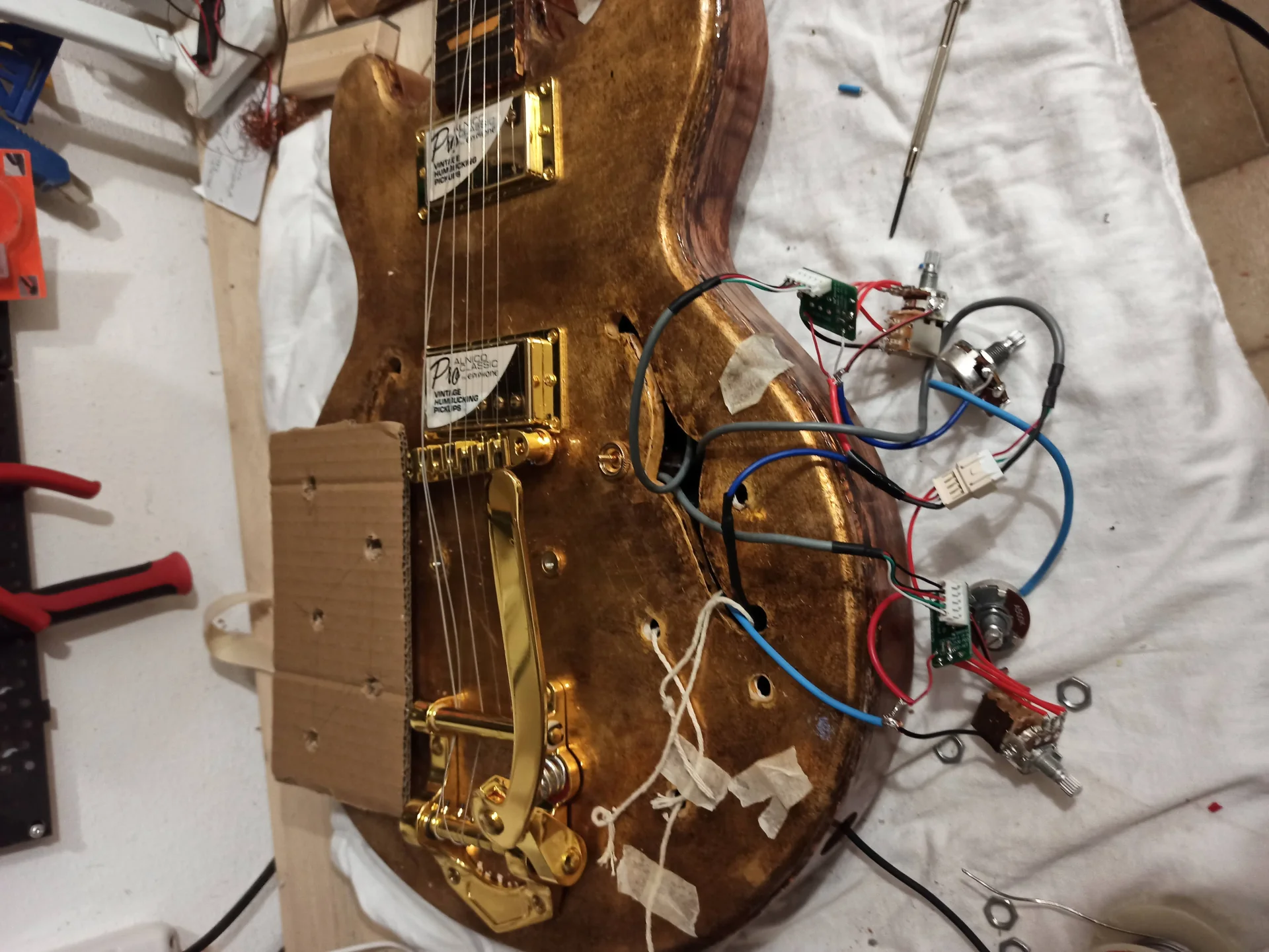
This circuit illustrates the basic installation of a single 4-conductor humbucker pickup, configured in standard series mode to maximize output power and hum-cancelling effect.2
Wiring diagram


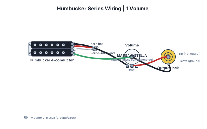
Download the SVG diagram and use it as a reference while soldering. The star ground is the central point: all ground wires must converge there.
How to read the diagram
It consists of a 4-conductor humbucker pickup and a logarithmic volume potentiometer of .3 Keeping the potentiometer with the terminals facing downwards, the standard color coding of the conductors is applied (e.g., Seymour Duncan standard) 8:
Practical steps
- Prepare the components and check the values of potentiometers and capacitors.
- I soldered the hot wires following the diagram, avoiding unnecessary jumpers.
- Connect all the masses to the indicated star point.
- Check the continuity between the bridge, jack and potentiometer covers with a multimeter.
- Test the instrument and fix any buzzing.
Tips to avoid buzzing
Avoid the ground loopIf the potentiometers are on a common metal shield, do not solder ground wires between their caps. Use an open "C" or "horseshoe" path and connect each ground to the star center. For more information on modifications, see also guitar modification guide.
FAQ
Which potentiometers should I use?
It depends on the pickup: single-coil generally 250k, humbucker 500k, active 25k.
Can I use a different capacitor?
Yes, but the value changes the cutoff frequency of the tone. Higher = darker sound.
See also
Wiring diagrams library
No diagrams found.
 English
  Italiano
Stuck on your build?
If you ran into the same problem or have a question, drop it in the comments. I read and reply to every one.
Write a comment