

Coil tap: intermediate tap on single coil
How many times have we found ourselves holding a guitar, perhaps a Stratocaster or a Telecaster, and thought: “The sound of this single coil is nice, but sometimes I’d like something a bit more… vintage? Less aggressive? More crystalline?” Well, you’re not alone. It happens often, especially if you use modern high-output pickups. Years ago, when I started tinkering with the electronics of my guitars in the garage, I found myself with a Telecaster that had a bridge pickup a bit too “nasty” for my taste in certain contexts. I wanted to keep it for when I needed punch, but I also wanted a more delicate, more traditional Tele nuance. That’s where I discovered the world of electronic modification and, in particular, the magic of the coil tap. It's not a very complicated concept, I assure you. You don't need to be electronic engineers or have a NASA lab. You need a bit’ of patience, a soldering iron and the desire to understand how things work. If I managed it, who burned more potentiometers than I correctly soldered at the beginning, you can do it too.Coil Tap: what it is and why it's not a Coil Split
The “Why” behind the sound: Resistors, Inductances, and Wire Turns
Okay, I know that for many, the word “electronics” gives them hives. But trust me, understanding the basics of as how a pickup works will help you tinker without fear and understand what you’re doing. It’s not magic, it’s physics. A pick-up is fundamentally a transducer. It takes the vibrations of the strings (mechanical energy) and transforms them into an electrical signal. How does it do it? Well, there’s a magnetic field created by the magnets, and when the string vibrates within this field, it induces an electrical current in the coil of wire wrapped around the magnets. It’s Faraday’s law, nothing transcendental. The amount of wire wrapped around the magnets is crucial. The more turns there are:

- Increases the resistance (measured in Ohm). A higher resistance means that the signal has more “difficulty” passing, but it is not the only factor.
- Increases theinductance (measured in Henry). Inductance is the ability of a coil to oppose changes in current. It is the most important factor for the tonal "character" of a pickup. Higher inductance tends to emphasize mid and low frequencies, making the sound "fatter" and with a higher output.
- Lower resistance.
- Lower inductance.
- Lower signal output.
- A brighter sound, with less emphasis on mids and lows, and greater clarity on high frequencies.
Enjoying this article? Subscribe to the newsletter: one email a week, zero spam.
Subscribe →What you need for a Coil Tap: Components and Garage Tools
Alright, the theory is settled. Now let's move on to practice. You won't need surgical instruments, but a good hobbyist kit is essential. And a bit of courage, of course. I remember the first time I soldered a potentiometer, my hand was shaking like a mad blender. Then, with practice, everything becomes easier.Required Components:
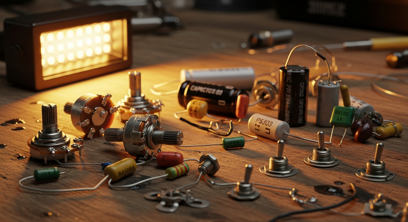
- Single Coil Pickup with Intermediate Tap: This is the key point. Not all single coils can be tapped. The pickup must have been designed with an additional output wire, specifically the “tap wire”, connected to an intermediate point on the coil. Usually, in addition to the two standard wires (one for the signal and one for the mass/ground), there
‘s a third, often of a different color. If your pickup doesn't have it, you can't tap it, period. - Switch (Selector): To activate or deactivate the tap. Here you have several options, depending on your preferences and the space available in the guitar body:
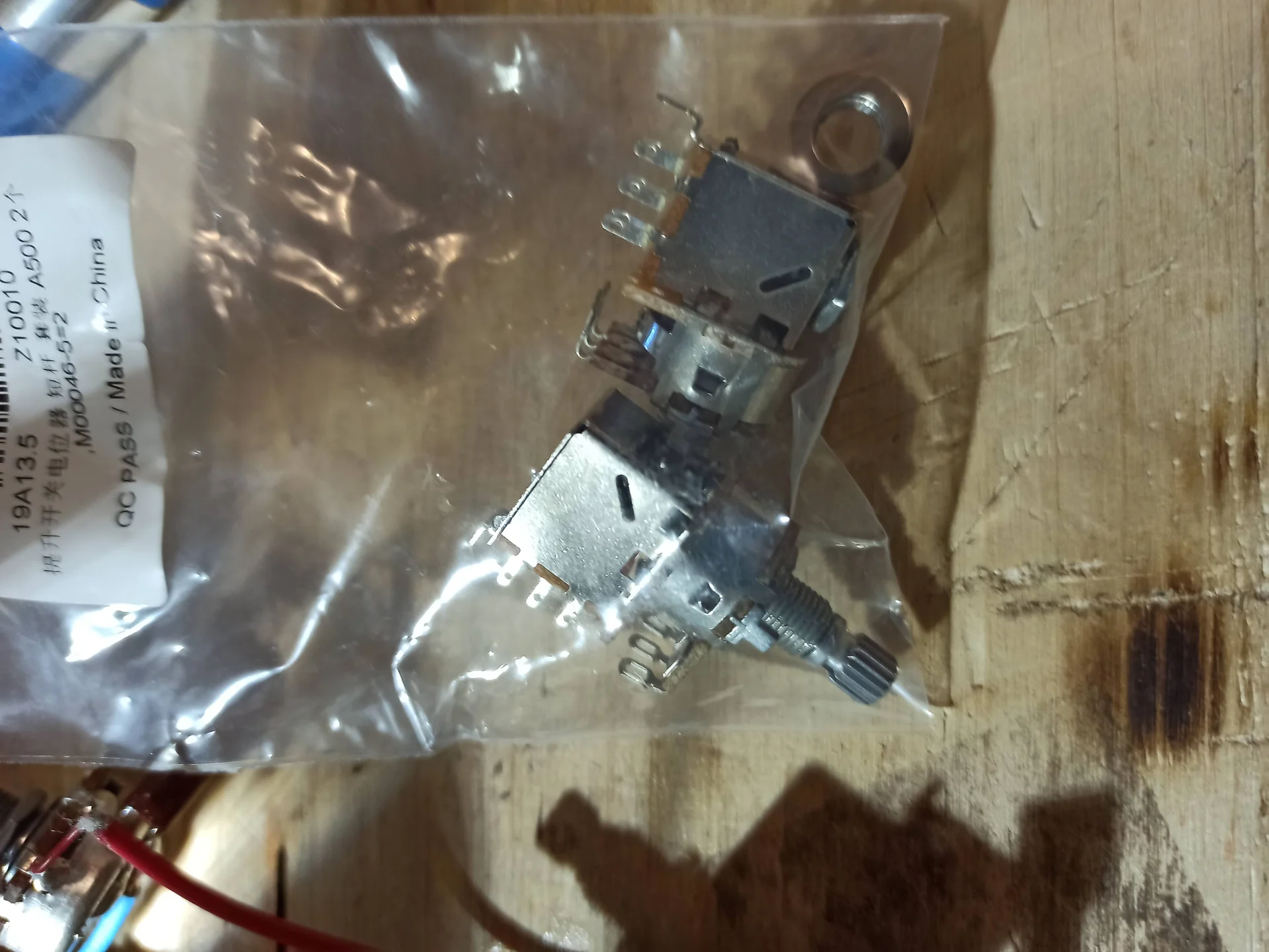
- Push/Pull or Push/Push Potentiometer: This is the most common and cleanest solution, as it doesn't require drilling additional holes in the body. The potentiometer functions normally for volume or tone, but by pulling it (push/pull) or pressing it (push/push), an integrated switch is activated. They are easy to find and relatively inexpensive.
- Mini Toggle Switch: If you have a free hole on the pickguard or body, or if you are willing to make one, a small toggle switch can be a robust and immediate solution. Make sure it's a DPDT (Double Pole Double Throw) for our purpose.
- Electrical Wire: Good quality, possibly shielded, for connections inside the cavity. A 22 AWG is perfect.
- Solder: Lead-free is better for your health and the environment, but it requires a soldering iron with a higher temperature.
- Heat Shrink Tubing: Essential for insulating solder joints and giving a professional look. Do not use electrical tape, for heaven's sake. After a while, it dries out and makes a mess.
Essential Tools:
- Soldering Iron: You don't need a very expensive model. A 30-50W soldering station with temperature control is ideal. A fine tip is a must for precise work.
- Desoldering Pump or Desoldering Braid: To correct any errors. And believe me, you will make mistakes. It's normal.
- Digital Tester (Multimeter): Essential for checking continuity, resistance, and identifying pickup wires. You can find inexpensive ones that do their job perfectly.
- Screwdrivers and Pliers: For disassembling and reassembling the guitar.
- Wire cutters and strippers: For cutting and stripping cables cleanly.
- Goggles: Splashing solder fragments are no joke for the eyes.
- Bench fan or fume extractor: To avoid breathing solder fumes. Health first.
Identify the wires and the conceptual diagram
Before you start soldering, we need to understand what we have. The pickup with coil tap will have three wires, in addition to any shielding (ground). Usually, wire colors follow a standard, but it's not a strict rule. It's always good to check.
- One wire will be the "start" of the coil (often the ground, or at least the starting point).
- One wire will be the "finish" of the coil (the end point, the one that goes to the selector or potentiometer).
- One wire will be the "tap", the intermediate tap.
- Set the multimeter to “resistance” mode (Ohm).
- Take one lead of the multimeter and connect it to one of the three pickup wires.
- With the other lead of the multimeter, touch the other two pickup wires in turn.
- You should get two resistance readings. One will be lower than the other. The wire that gave you the lower reading, when paired with the first wire, is the tap. The wire that gave you the higher reading is the finish. The first wire you used, if paired with both the tap and the finish gave you a resistance reading, is the start (or ground).
- I connect the red lead of the multimeter to the Black wire.
- I connect the black lead to the white wire: I read 7k Ohm.
- I connect the black lead to the red wire: I read 12k Ohm.
Solder without fear: Step-by-step guide for Coil Tap
Now it's time for action. If you are not experienced in soldering, do some practice on a piece of scrap wire first. A good solder joint is shiny, "volcano-shaped", and does not need to be "drowned" in solder.Steps for installation:
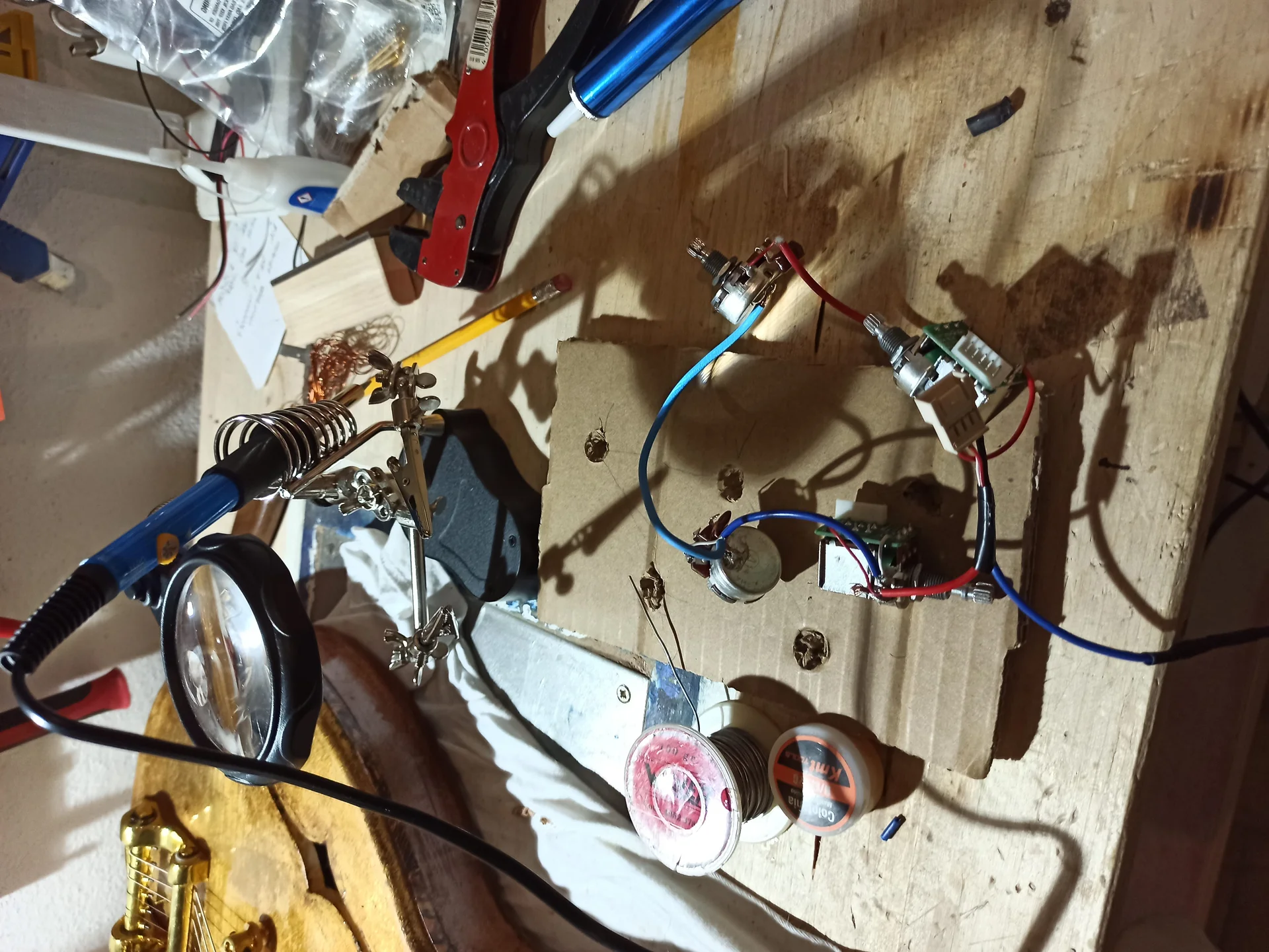
- Prepare the Workbench: Clean space, good lighting. Place a protective mat to avoid damaging the guitar body. Keep all tools within reach.
- Disassemble the Pickguard/Controls: Disconnect the wires of the pickup you want to modify. Take a photo before disassembling everything; it will be useful for reassembly. Do not underestimate this step. I've lost count of the times I thought "I'll remember it" and then found myself with a tangle of wires.
- Identify the Pickup Wires: As explained before, use the multimeter to identify the "start" (or ground) wire, the "tap" and the "finish". Mark them with small pieces of colored tape if it helps.
- Prepare the Switch: If you use a push/pull potentiometer, mount it in place of an existing potentiometer (volume or tone). If you use a mini toggle, make the hole in the desired spot (measure twice, drill once!).
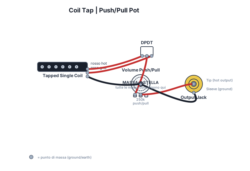
- Simplified Wiring Diagram (for a Push/Pull):
- The “start” wire of the pickup (the one with the lowest resistance compared to the other two) is soldered to the circuit ground (usually the back of the potentiometer).
- The “finish” wire of the pickup (the one with the highest resistance) should be soldered to one of the outer terminals of the push/pull switch (for example, pin 1 of the upper row).
- The “tap” wire of the pickup (the one with intermediate resistance) should be soldered to the other outer terminal of the push/pull switch (for example, pin 3 of the upper row).
- The center terminal of the switch (pin 2 of the upper row) will be the pickup's signal output, and should be soldered to the point where the pickup's output wire was previously connected (e.g., to the center terminal of the volume potentiometer, or to the input of the pickup selector).
- Repeat the operation for the other row of DPDT pins (if the switch is a DPDT), connecting the corresponding pins in parallel or leaving the terminals of the second row unused if your switch is an SPDT. Generally, a DPDT is more versatile and offers more wiring options. For a simple SPDT coil tap, it's enough. To avoid confusion, imagine the switch as two parallel “tracks”. If you use a DPDT and don't need both sides, you can connect the two sides in parallel for greater reliability, or simply use one.
- Welding:
- Heat the terminal where you need to solder and the wire well.
- Apply solder to the contact point, not to the tip of the soldering iron.
- Once soldered, make sure the connection is solid and shiny.
- Use heat shrink tubing to insulate each solder joint. It's a detail that makes a difference in terms of reliability and cleanliness.
- Continuity Test: Before reassembling everything, use the multimeter. Verify that there is continuity between the pickup output wire (from the center of the switch) and the “finish” wire when the switch is in one position, and with the “tap” wire when the switch is in the other. Also, check for unwanted short circuits.
- Reassemble and Test: Reassemble the controls, reconnect everything. Connect the guitar to the amplifier and test. Listen for the differences between the two switch positions. If all went well, you should hear a fuller and more powerful sound in one position, and a brighter and more transparent sound in the other.
Build better. Subscribe for updates, guides and free ebooks.
Subscribe →Troubleshooting and Tips from “Vecio” of the Garage
Even if everything seems simple, sometimes things don't go as planned. Here are some tips for when something doesn't sound right.Common Problems and Solutions:
- No Sound or Very Weak Sound:
- Cold Welding: Check all solder joints. They must be shiny and solid. A dull or grainy solder joint is a “cold” solder joint and does not conduct well. Redo it.
- Wrong Wires: Have you correctly identified the “start”, “tap” and “finish”? Try again with the multimeter.
- Broken Ground: Make sure all ground points are connected correctly. A poorly connected ground is an endless source of problems.
- Excessive Noise (Hum):
- Grounding Problems: Once again, ground is your best friend (or worst enemy). Make sure all components are properly grounded, and that the pickup's shielding cable is grounded if present.
- Faulty Soldering: A cold solder joint can also introduce noise.
- Unshielded Cables: If the cables inside the cavity are too long and unshielded, they can pick up interference.
- Non-functioning Switch:
- Wrong Wiring: Review your switch's diagram. The terminals must be connected correctly. A DPDT has two independent sections, make sure you've used the right one or wired them in parallel.
- Defective Switch: It happens. Sometimes a component is faulty from birth. If you've checked everything else, try replacing it.
Practical Tips:
- Cleaning: Keep your soldering iron tip clean. Use a damp sponge or steel wool. A dirty tip doesn't solder well.
- Temperature: Don't hold the soldering iron on components for too long. Heat can damage potentiometers, capacitors, and even the thin wires of the pickup. A few seconds are enough for a good solder joint.
- Organization: Use wire color codes. If there isn't one, label them yourself. It will save you a lot of headaches.
- Patience: Don't rush. It's a hobby, not a race. If you feel frustrated, take a break and come back later. I've spent entire evenings staring at a circuit before understanding the error.
- Document: Take photos of the original wiring and each step. They will be your salvation if you need to go back. And if the job turns out well, they might also be useful to others who want to try the same modification!
- Useful external source: For the most common wiring diagrams and component specifications, the website of Seymour Duncan is a fantastic resource. It offers hundreds of diagrams for every type of pickup and configuration, including those with coil tap.
Conclusions: The Satisfaction of “Made by Me”
The coil tap is one of those modifications that opens up a world of sonic possibilities with a relatively small investment. It allows you to get incredible versatility from a single pickup, going from a powerful and full-bodied sound to a more delicate and crystalline one with a simple click. It's like having two guitars in one, or at least two “voices” for the same instrument. The first time I heard the tonal difference on my Telecaster after installing the coil tap, I had a moment of pure satisfaction. That brighter, more open sound was exactly what I was looking for, and knowing I had created it with my own hands, in my garage, is priceless. Not just for the practical result, but also for the awareness you gain. Every time I play that guitar, I feel a different, deeper connection. Don't be scared by technical terms or the fear of ruining your guitar. With a bit of study, the right tools, and a lot of patience, you can do incredible things. And if you make a mistake? Well, you learn. You desolder, you redo. That's how you grow, even in the world of DIY electric lutherie. So, if you have a single coil that sometimes seems a bit too “bloated” or one-dimensional, and if you're ready to get your hands dirty, the coil tap could be your next adventure. Try it. Your guitar (and your ears) will thank you.See also
Wiring diagrams library
No diagrams found.
Download the Luthier Survival Kit
Free PDF with checklist, problem-cause table and project card template.
 English
  Italiano
Stuck on your build?
If you ran into the same problem or have a question, drop it in the comments. I read and reply to every one.
Write a comment