

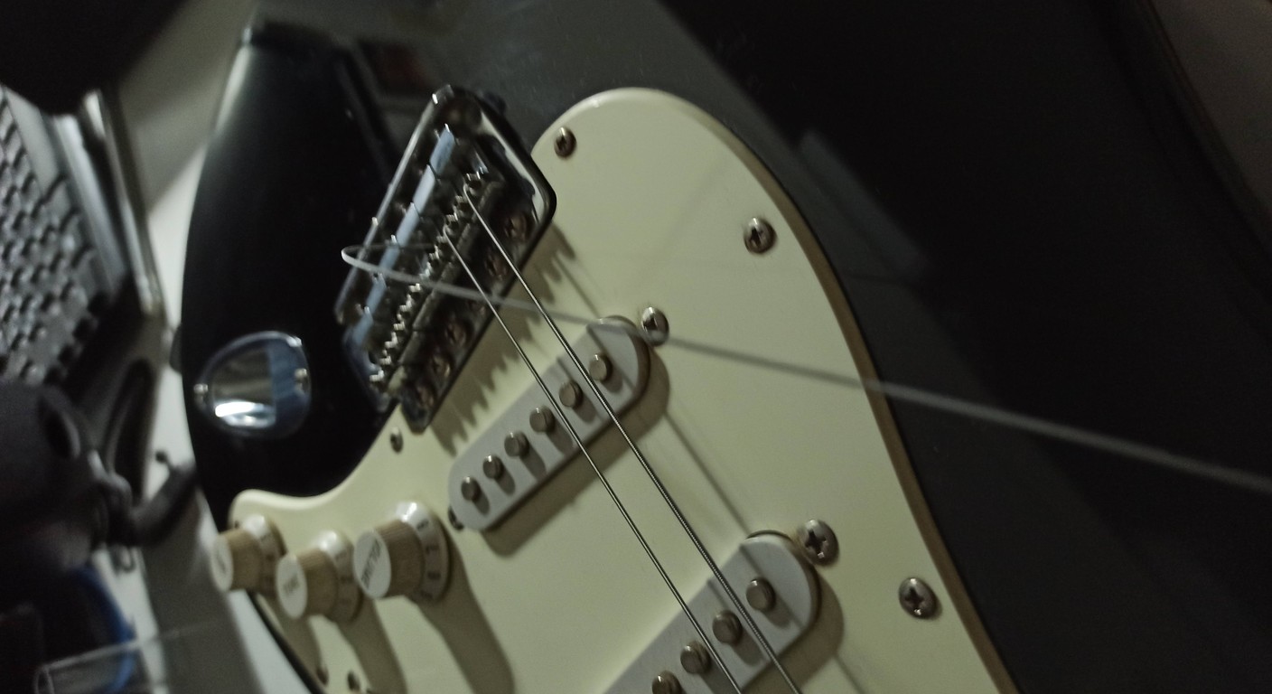
Do You Have a 3 Pickup Guitar Wiring Diagram? Here Are 3 Solutions
When I started getting my hands on guitars, the first thing that scared me wasn't so much routing a body or leveling frets. No, the real bugbear was electronics. That flood of wires, potentiometers, capacitors and, above all, the schematics. It seemed like stuff for aerospace engineers, not for someone who at most knew how to change a light bulb.And instead, after a few botched solders, a few pickups mounted backward, and a couple of short circuits that made me fear for the life of my amplifier, I understood one thing: it's not as complicated as it seems. It just takes patience, a decent soldering iron, and, above all, understanding the Why behind the as. Not just replicating a schematic, but understanding its logic.
If you have a guitar with three pickups, maybe a Stratocaster, a Telecaster with a third pickup in the middle, or perhaps a more custom project with three humbuckers, you know that the sonic possibilities are many. But to unlock them all, you need a scheme of wiring for a three-pickup electric guitar that works and, perhaps, gives you something extra. Today we'll look at three different approaches, from classic to more advanced, to get the most out of your configuration.
Three Pickups: Why Complicate Life? And How to Simplify It.
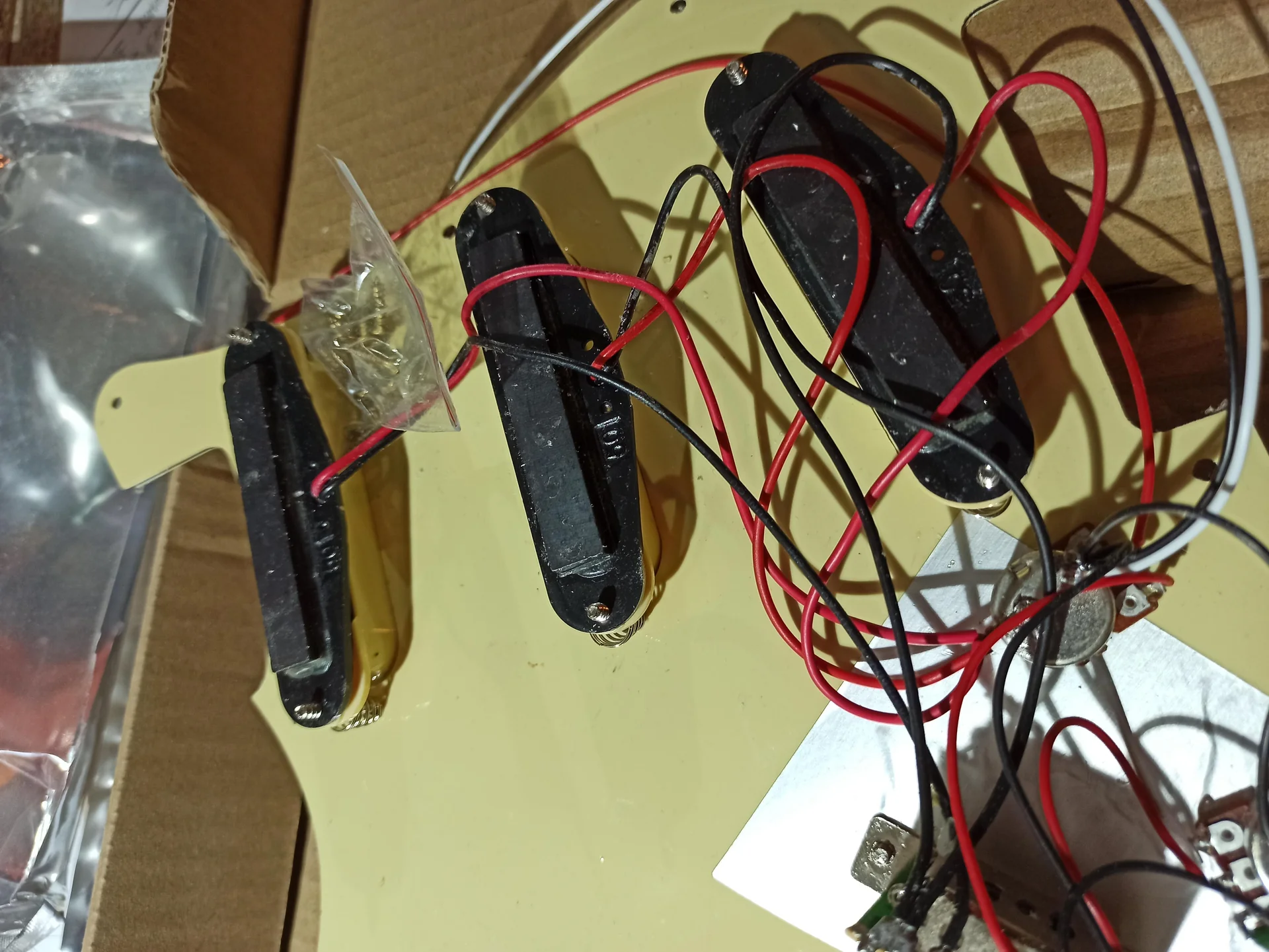
Before diving into the schematics, let's do a quick review of the basic components you'll find in any electrical system of a three-coil guitar. Understanding what each piece does will help you not feel lost. Pick-up: They are the “microphones” of the guitar. They transform the vibration of the strings into an electrical signal. They can be single coil (single coil, bright but noisy sound) or humbucker (two coils out of phase, fuller sound and less noise). When you connect them, the “hot” wire goes to the signal, and the “cold” (ground) wire goes to ground.
Potentiometers (Pots): They are variable resistors. You use them to control volume (master volume) and tone (master tone or separate tones). The pot value (e.g., 250kΩ, 500kΩ) is crucial.
Volume: Generally, 250kΩ are used for single coils, and 500kΩ for humbuckers. This influences the amount of high frequencies that are “dumped” to ground. With a higher value, more highs pass through.
Tone: Here too, 250kΩ or 500kΩ. Their function is to work with a capacitor to cut high frequencies.
Capacitors (Caps): These small cylinders or discs are the allies of tone potentiometers. They serve to “filter” high frequencies to ground, making the sound darker. Their value (e.g., 0.022µF, 0.047µF) determines how many high frequencies are cut and with what slope. A 0.022µF is very common in guitars, especially Stratocasters.
Selector (Switch): The heart of your wiring layout for a three-pickup guitar. It allows you to choose which pickup to use, or which combinations. The most common are 3-way (Telecaster) or 5-way (Stratocaster). We will see how a 5-way is fundamental for the three pickups.
Output Jack: The final point, where the guitar signal exits to go to the amplifier. It has two contacts: tip (hot signal) and sleeve (ground).
Soldering? It's not rocket science. Get a 30-40W soldering iron, good quality solder (60/40 or lead-free), and practice on some scrap wire. The goal is to create a solid, clean connection, where the solder melts well and covers the surfaces. It shouldn't look like a cold, gray ball of solder. It should be shiny and smooth. If it's not, reheat and redo it. Nobody is born an expert.
Garage Tip: Before soldering, clean the potentiometer terminals and wires well. A small filing or a pass with fine sandpaper helps the solder adhere better. And don't be afraid to use a bit of electrical tape or heat shrink tubing to prevent accidental short circuits after you're done.
The Standard Configuration: The Workhorse
Advertisement

ENYA XMARI Smart Electric Guitar, 39" Beginner Kit with Built-in 4 Effects | Carbon Fiber Body, HSS Pickups, USB-C Recording, Built-in DSP Chip, Headphone Output, App Control, Silent Practice, Black
See on Amazon

The wiring diagram for a three-sensor guitar most common for a Strat includes:
Three single coils (neck, middle, bridge).
A 5-position selector.
A general volume potentiometer (master volume).
Two tone potentiometers: one for the neck pickup and one for the middle pickup. The bridge pickup traditionally has no tone control. ### How the 5-Way Selector Works This switch is the brain of the operation. It has several tabs (terminals) where the pickups and tone controls are connected. Usually, it has 8: 3 for pickup input, 3 for position output, and 2 jumpers to connect the commons.
The selector positions work like this: 1. Bridge: Only the bridge pickup is active. Sharp sound, ideal for aggressive riffs and solos. 2. Bridge + Middle (Bridge + Middle): The two pickups are active together, in parallel. This produces a very characteristic “quack” or “out of phase” sound (it's not a true out of phase, but a more scooped and nasal sound), great for funk or clean rhythms. 3. Center (Middle): Only the middle pickup is active. A balanced, versatile sound, good for rhythms and solos. 4. Middle + Neck (Middle + Neck): Here too, two pickups in parallel, with a sound similar to position 2 but rounder. Another classic for funk or clean sounds. 5. Neck: Only the neck pickup is active. Warm, round sound, great for blues, jazz, and melodic solos. ### Key Components and Connections Pick-up: The “hot” wires of each pickup go to their respective input terminals on the 5-way selector. All ground wires go to the main circuit ground (usually on the back of a potentiometer).
Master Volume: The output signal from the selector (the “common” of the switch) goes to the input terminal of the volume pot (usually pin 1 or 3, depending on how you view it). The central terminal of the pot (wiper) is the volume output, which goes to the jack. The other terminal goes to ground.
Tones: Each tone potentiometer receives the signal from the pickup it controls (often taken directly from the selector terminal where the pickup is connected). The central terminal of the pot goes to one end of the capacitor, the other end of the capacitor goes to ground.
For values, with single coils, a 250kΩ master volume and two 250kΩ tones are the most common choice. Capacitors, 0.022µF (microfarads) are standard.
This 3 pickup guitar wiring diagram is the easiest to implement and will immediately give you a familiar and versatile sound. If you are thinking of modify your guitar for the first time, starting here is a great starting point. It allows you to understand the basics without going crazy.
Mimmo's Anecdote: The first time I wired a Strat, all my ground wires were tangled. It looked like a ball of spaghetti. It worked, but it hummed like a hive of angry bees. I learned to do a good “star ground” (all ground wires converge at a single point) after that experience. Believe me, it makes a difference!
Enjoying this article? Subscribe to the newsletter: one email a week, zero spam.
Subscribe →More Options, Same Number of Pickups: Split and Series/Parallel
Ok, the standard configuration is great, but what if you want to push it a bit further? Maybe you have an HSH (Humbucker-Single-Humbucker) or SSH configuration, or even three humbuckers. This is where push-pull potentiometers or mini-switches come into play, allowing you to manipulate the pickups in interesting ways.The idea is to add functionality to the same 3-pickup guitar circuit, without increasing the number of knobs on the body.
Coil Splitting (or Tapping)
This is one of the most popular modifications for humbuckers. A humbucker, as the name suggests, has two coils. Coil splitting allows you to “turn off” one of the two coils, transforming the humbucker into a single coil. Why do it? It gives you the brightness and “twang” of a single coil, while keeping the humbucker pickup when a fuller, quieter sound is needed. It's like having two pickups in one. How does it work? Modern humbuckers have 4 conductors plus ground. Two wires are the beginning and end of the first coil, another two are the beginning and end of the second coil. To do the splitting, the connection between the two coils is “interrupted”, sending the junction point of one of the two to ground. Usually, a push-pull potentiometer is used: when you pull the knob, you activate the splitting.Series/Parallel (Series/Parallel)
This modification is a bit less common but equally powerful. You can apply it to a single humbucker (changing the way its two coils are connected) or to two single coil pickups when they are activated together. Humbucker Coils: Series (Standard): The two coils are connected in series. The sound is thicker, with more output and bass.Parallel: The two coils are connected in parallel. The sound is brighter, with less output and a more open frequency response, almost like a single coil but without the noise. Two Single Coils (e.g. Neck+Middle): Parallel (Standard): The two pickups are wired in parallel (as in Strat positions 2 and 4).
Series: The two pickups are wired in series. This increases output and volume, making the sound 'fatter' and humbucker-like. It's an interesting modification to get a sonic boost without pedals. How is it implemented? Here too, push-pull potentiometers or mini-switches are the ideal solution. A single push-pull can control the splitting of a humbucker, or the series/parallel wiring of two pickups activated together. You can have one push-pull for each humbucker, or a master one for all.
This solution requires a three-pickup electric guitar wiring diagram a bit more elaborate, because push-pulls have more terminals to solder. But the principle is the same: follow the lines, understand what each connection does. Don't be scared of the extra wires, they are just extra options for your sound.
Practical Tip: When using push-pulls, make sure you have enough space in the guitar's cavity. Sometimes, with many wires and capacitors, it can get a bit crowded. And remember to label the pickup wires if they are not already color-coded, it will save you a lot of headaches! You can find detailed diagrams for coil splitting and series/parallel on the websites of pickup manufacturers like Seymour Duncan or DiMarzio. For example, you can check out the diagrams on the [Seymour Duncan](https://www.seymourduncan.com/resources/wiring-diagrams) website. They are a very reliable source.
Experimenting with Pickups: Independent Switches and Blender Pots
If you're the type who loves to push things to the limit, or simply want granular control over your sound, there are solutions that deviate from the classic 5-way selector. Here we're talking about a wiring diagram for a three-sensor guitar that allows you to combine pickups in unconventional ways.Independent On/Off Switches
Imagine having a separate switch for each pickup. This allows you to turn each pickup on and off individually, creating combinations that a 5-way selector cannot offer. Why is it cool? All combinations: You can have Neck+Bridge (the 'Telecaster' position on a Strat), Neck+Middle+Bridge all together, or any other combination.Brian May Style: Brian May's Red Special uses a similar system, with on/off switches and phase switches, to achieve its unique sounds. You won't need to reach that level of complexity, but that's the idea. How is it done? You need three mini-toggle switches (DPDT, Double Pole Double Throw, they are perfect because they have enough terminals to manage the on/off and grounding of the pickup when it's off). Each pickup is connected to a switch, and the output of each switch then goes to the volume potentiometer (or to the selector if you want to keep some functions).
This solution radically changes your three-pickup electric guitar wiring diagram, eliminating or complementing the traditional selector in favor of more direct control. It requires drilling holes in the body or pickguard for the switches, so evaluate carefully before proceeding.
Blender Pot
The blender pot is a knob that allows you to 'blend' the signal of one pickup with that of another, continuously, instead of a simple on/off. It is often used to add the neck pickup in a bridge position, or vice versa, gradually. How does it work? Instead of a tone potentiometer, you can install a blender pot. It works like a 'mix' that, when at zero, does nothing, and when you turn it, it starts to introduce the signal of another pickup. For example, you could have the selector in the bridge position, and by turning the blender, gradually add the neck pickup. Advantages: Infinite nuances: You don't just have fixed positions, but a continuous range of blends.Unique sounds: You can find the exact point where the two pickups perfectly complement each other.
A blender pot is a particular potentiometer (usually a balance pot or a pot with specific wiring) that is inserted into the circuit to partially bypass the selector or one of the pickups. It requires a bit more study of the wiring diagram for three pickups because its implementation can vary depending on the desired effect.
Garage Patience: I remember when I tried to install a set of on/off switches on a cheap guitar. I made the holes a bit crooked, and to fix it I had to enlarge the holes and use larger washers. It didn't come out perfect, but it sounded divine! The important thing is that it works and that you are happy with the result. Every mistake is a lesson.
Garage Patience: Don't Be Afraid to Make Mistakes
We have seen three ways to approach the wiring of a three-pickup guitar, from the most classic to the most adventurous. Regardless of the solution you choose, there are a couple of things I've learned the hard way and want to share. 1. Check, Double-Check, Then Solder: Before picking up the soldering iron, look at the diagram. Then look at it again. Then check the components. Are the values correct? Are the wires long enough? Once soldered, it's a mess to disassemble everything. 2. Mass is Everything: A good ground connection is essential to reduce noise. Make sure that all components requiring ground (the back of the potentiometers, the pickup ground wires, the jack sleeve) are solidly connected to each other and then to the guitar bridge. 3. Clean and Strong Solders: A cold or weak solder joint is a recipe for problems. If a wire comes loose while you're playing, it's frustrating. Practice soldering; it should be shiny and form a solid “mound”. 4. Test at Every Step: If possible, test the circuit as you build it. Connect a pickup, test. Connect the volume, test. This helps you isolate any problems before everything is closed in the cavity. 5. Don't Be Afraid to Make Mistakes: I said it at the beginning and I'll repeat it. I've burned potentiometers, short-circuited, soldered wires backward. Every time I learned something. That's how you get good. There isn't a DIY luthier who hasn't messed up at least once.Building or modifying your guitar's electronics is an incredibly rewarding experience. When you connect your work to the amplifier and hear that sound come out, that sound that you you created with your own hands, it's an invaluable feeling. It's not just an object, it's a part of you.
So, grab your soldering iron, choose your three-pickup electric guitar wiring diagram favorite and get to work. The worst that can happen is that you learn something new. And that, trust me, is always a good thing.
See also
Download the Luthier Survival Kit
Free PDF with checklist, problem-cause table and project card template.
 English
  Italiano
Stuck on your build?
If you ran into the same problem or have a question, drop it in the comments. I read and reply to every one.
Write a comment