

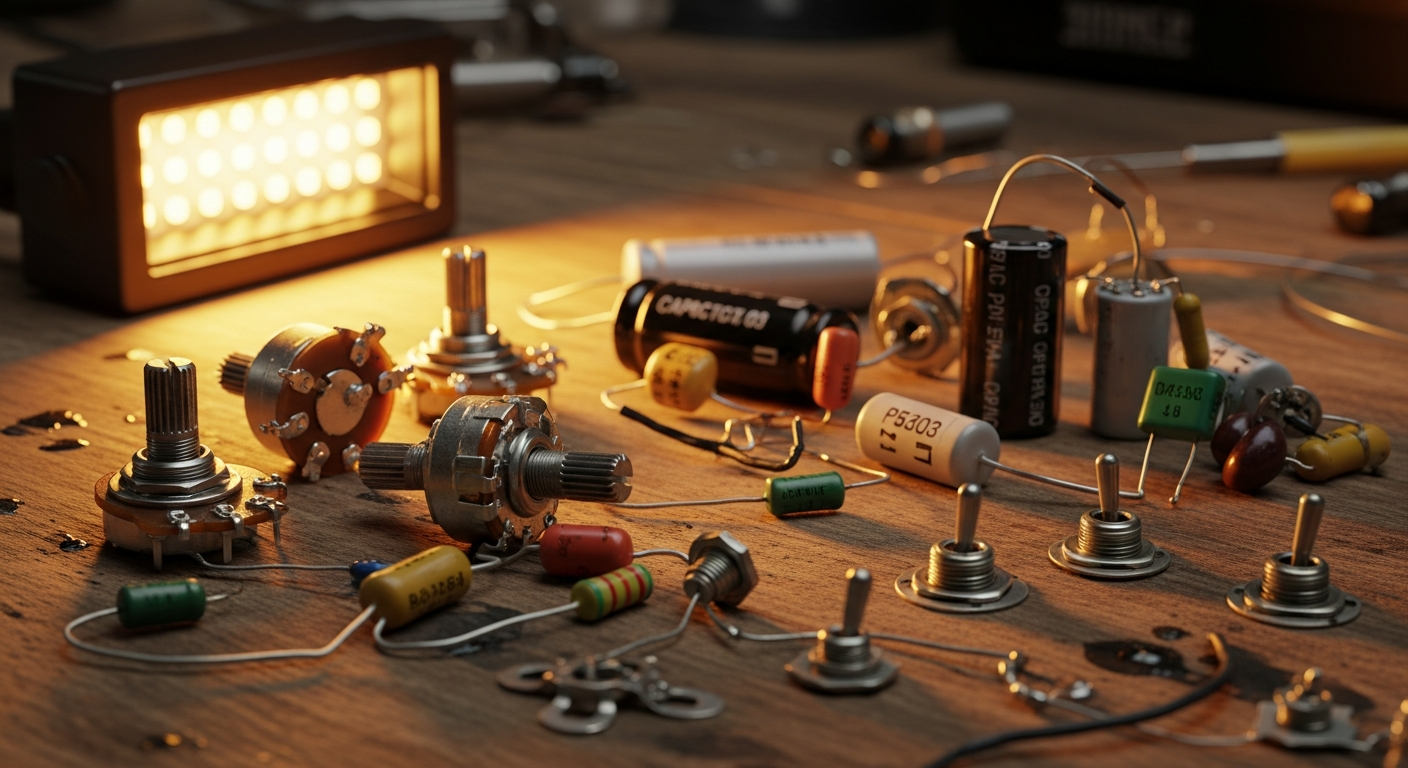
Edit Guitar Coil Split: Practical Diagram.
So, let's get straight to the heart of the matter: the guitar coil split. If you're here, you probably have an humbucker that sounds awesome, but sometimes you miss that single coil “twang”, that brightness that makes you think of a Strat or a Tele. I've been there too. For years I played guitars with powerful humbuckers, thinking that was “my sound”. Then, one day, I stumbled upon an old wiring diagram, one of those handwritten ones, and I thought: “But why not try to get a different sound out of this pickup?” I'm not a professional luthier, let's be clear. I'm someone who, like you, has spent hours in the garage with a soldering iron in hand, sometimes with disastrous results, other times with the satisfaction of having created something unique. I've burned potentiometers, soldered wires in the wrong place, and once I even swapped the ground for the hot, with a hum that sounded like an alien invasion. But it was precisely from those errors that I learned. And I understood that the coil split modification is not stuff for electronics wizards, but a simple trick that can totally change the versatility of your guitar. If the idea of messing with your guitar's electronics scares you, I understand. The first time I opened the control cavity, it looked like a snake's nest. Wires everywhere, solders that looked like they were made by a three-year-old. But I assure you that, with a little patience and the right tools, you can do it too. The goal of this article is precisely that: to give you a clear, practical guide, without too many frills, to achieve your coil split and discover new sounds.
What is Coil Split and Why Should You Want It
Let's make one thing clear right away: we're not talking about magic, but physics applied to sound. An humbuckers is, by definition, composed of two coils of wire wound in opposite directions and wired out of phase. This ingenious stratagem serves to cancel the 50/60 Hz hum that afflicts single coil pickups, hence the name “hum-bucker” (literally “hum-killer”). The result is a fuller, warmer sound, with a higher output, perfect for rock, metal, and genres that require sustain and power. The downside is that, sometimes, such a full sound can be a bit “muddy” or “dark” in certain contexts. This is where the coil split. In practice, it involves deactivating one of the two humbucker coils, leaving only the other active. The pickup behaves, to all intents and purposes, like a single coil. It's not a “true” single coil, because the impedance and magnetic field were designed for two coils, but the sonic result is surprisingly similar.
The Sonic Advantages of a Coil Split
The main benefit of this modification is versatility. Imagine having a guitar with a bridge humbucker for your nastiest riffs, and then, with a simple “click”, being able to switch to a brighter, crystalline sound, with that “glassy” character typical of single coils. This opens up a world of sonic possibilities, allowing you to span different genres without having to change guitars. That “twang” you're looking for for country, the clarity for clean arpeggios, or that slightly more “thin” sound for certain funk passages, suddenly become within reach. The pickup's output drops drastically when split, which also means less gain on your amplifier, useful for cleaning up the sound or getting a lighter crunch.
The Disadvantages (or Compromises)
Obviously, not all that glitters is gold. When you turn off a coil, you also lose its hum-canceling ability. So yes, your split pickup will hum like a traditional single coil. It's the price to pay for that extra brilliance. Furthermore, the sound will be less powerful, more mid-range, and with less bass compared to the full humbucker. Don't expect an identical Stratocaster sound, but rather an excellent emulation that will give you that single coil flavor. For many guitarists, however, the pros far outweigh the cons. I myself, after trying the coil split, I never looked back. Having the ability to choose between a big sound and a brighter one, with the same guitar, is a game changer, especially if you play in different situations or are trying to cover a wide range of sounds.
What You Need: Essential Tools and Materials


Before you start tinkering with your guitar, it's essential to have the right tools and necessary materials. Don't improvise: good preparation will save you a lot of headaches (and ugly solders).
Indispensable Tools
- Soldering Iron: You don't need a soldering station costing thousands of euros. A 25-40 Watt fine-tip soldering iron is more than sufficient. Make sure the tip is clean and tinned (covered with a thin layer of solder) before each use. A dirty or oxidized tip does not transfer heat well.
- Pond: Use good quality solder, with a flux core. I recommend a thin diameter (0.6mm or 0.8mm) for precision work on guitar electronics. I find 60/40 solder (60% tin, 40% lead) or 63/37 (eutectic, melts at a lower and sharper temperature) works well. If you prefer not to use lead, there are also lead-free options, but they are a bit more difficult to work with.
- Desoldering Pump or Desoldering Braid: Essential tools to remove incorrect solders or to disconnect existing wires. The pump sucks up molten solder, the braid absorbs it by capillarity. Having both is ideal.
- Nippers and Wire Strippers: To cut and strip wires with precision. The thin-nose pliers are perfect for tight spaces.
- Screwdrivers: Slotted and Phillips, of different sizes, to open the control compartment and remove the pickguard or pickups.
- Multimeter (Tester): Your best friend in these operations. Fundamental for checking circuit continuity, identifying pickup wires, and verifying that there are no short circuits. Don't underestimate it: it will save you time and frustration.
- “Third Hand” (Optional but Recommended): A stand with clamps and a magnifying glass to hold wires or components steady while soldering. It frees your hands and makes the job much simpler, especially if you're a beginner.
- Safety Glasses: Always a good idea when working with heat and small pieces of metal.
Specific Materials for the Coil Split
- Push/Pull Potentiometer (or Push/Push): This is the most common and discreet method to add coil split. It's a normal potentiometer (volume or tone) with a DPDT (Double Pole, Double Throw) switch integrated into the shaft. By pulling or pushing the knob, you activate or deactivate the switch. Make sure to get the right value (A500k for humbuckers, A250k for single coils, but also for humbuckers if you want a slightly darker sound) and the correct shaft length (long shaft or short shaft) depending on the thickness of your guitar's top.
- DPDT Toggle Switch (Optional): If you don't want to replace an existing potentiometer or if you have enough space on the pickguard or guitar body, you can install a separate DPDT switch. Here too, “DPDT” is the key specification: it means it has two “poles” (two independent circuits) and two “throws” (each pole can connect to two different positions). This gives you the necessary flexibility for coil split.
- Electrical Wire: A bit of 22 AWG stranded wire (stranded, not rigid) is useful for internal connections. Different colors can help you keep order.
- Heat-shrink or Electrical Insulating Tape: To insulate exposed welds and prevent short circuits. Heat shrink is cleaner and more professional.
An important note on potentiometers: “A” stands for “Audio Taper” (logarithmic), ideal for volume and tone control, as it follows the logarithmic perception of the human ear. “B” stands for “Linear Taper” (linear), sometimes used for volume but less common in the world of guitars.
Enjoying this article? Subscribe to the newsletter: one email a week, zero spam.
Subscribe →Understand Your Humbucker: How Many Wires Does It Have?
This is the crucial point. Not all humbuckers can be easily split. The possibility of performing the coil split it depends entirely on how your pickup is wired internally.
2-Wire Humbucker
If your humbucker has only two output wires (plus the shielding, which counts as ground), it means that the two coils are already connected in series internally and there is no way to access the junction point between them. In this case, the coil split it is not possible without physically modifying the pickup, which I strongly advise against if you do not have experience with pickup winding.
3-Wire Humbucker
Quite rare, but they exist. Some vintage humbuckers or specific models can have three wires: one for the “hot” of the first coil, one for the “hot” of the second coil and a common ground wire. Alternatively, a common “hot” and two separate grounds. In these cases, the coil split it is possible, but requires careful study of the specific pickup scheme.
4-Wire Humbucker (and Ground)
This è the Holy Grail for those who want the coil split. The vast majority of modern humbuckers, especially aftermarket ones from brands like Seymour Duncan, DiMarzio, or even many stock pickups, are 4-conductor, plus a fifth wire (or the shield) for the general ground. These four wires represent the beginning and end of each of the two coils: Coil 1 (North Coil): It usually has a “start” wire and a “finish” wire. Coil 2 (South Coil): This one also has a “start” wire and a “finish” wire. To make the humbucker work normally, the two coils are connected in series (or sometimes in parallel, but series is the standard) by joining the finish of one with the start of the other. The two remaining wires become the “hot” (signal) and the “ground” (ground) of the pickup.
Identify the Colors of the Wires
The problem is that there is no universal standard for wire colors among different manufacturers. What for Seymour Duncan is the “hot”, for DiMarzio could be a coil “finish”. It is fundamental not to make assumptions. Here's how to proceed: 1. Search for your pickup's diagram: The first thing to do è to identify the exact manufacturer and model of your humbucker. Then, go to the manufacturer's website (e.g. Seymour Duncan wiring diagrams) and look for their 4-conductor wiring diagram. Lì you will find the color legend that will tell you which wire è the “start” of the North coil, which the “finish” of the South coil, and so on. 2. Use the multimeter (if you don't have the diagram): If you can't find the diagram or if the wires all look the same, the multimeter comes to the rescue. Set the multimeter to resistance measurement (Ohm, usually 20kΩ or 200kΩ). Take two random wires and touch the multimeter probes. If you see a value (e.g. 4k-8k Ohm for a single coil), you have found the two ends of a coil. If you read “OL” (Over Limit) or 1, it means there is no continuity between those two wires, so they do not belong to the same coil or are not connected. Once you have identified the two pairs of wires that form the two coils, you can figure out which è the “hot” and which the “ground” of the pickup when it functions as a humbucker (usually these are the wires that remain after joining the other two for the series). The crucial point for the coil split are the two wires that are joined to put the coils in series. These are the wires you will need to route to the switch. Remember: patience è the virtue of the fortunate. Take your time to correctly identify the wires. A mistake here means a pickup that doesn't work or sounds bad.
The Practical Diagram: How to Wire the Coil Split
Now that you know what you need and have identified your humbucker's wires, let's get to it. I'll guide you through the most common diagram, the one that uses a push/pull potentiometer. È my favorite because è discreet and doesn't require additional holes on the guitar.
For this example, we'll assume we have a 4-conductor humbucker plus ground, and we want to split the coil towards the bridge (or the “south” coil, depending on how è the pickup is mounted). The principle è the same for splitting the other coil.
**Wire Identification (example based on the Seymour Duncan standard, but always check yours!):**
Black: Hot (North coil start)
White: North coil finish
Red: South coil start
Green: South coil finish (usually soldered to ground for humbuckers)
Ground (bare wire): Overall shielding
In a standard humbucker, the White wire and the Red wire are joined and insulated, forming the junction between the two coils. The Black goes to the pickup selector/potentiometer, and the Green (and ground) goes to ground.
Steps for Coil Split with Push/Pull Potentiometer
The push/pull potentiometer has six terminals on the switch side: three for one “pole” and three for the other. Imagine two three-position switches side by side.
Locate the solder joint that connects the White and Red wires (or the wires that connect the two coils in your specific diagram).
Desolder these two wires from each other. If they were wrapped with tape or heat shrink, remove it carefully.
Strip them slightly if necessary, ensuring the conductors are clean.
When the potentiometer è in the “pushed” position (push), the White and Red wires are connected to each other, but are not connected to ground. In this way, the two coils are in series and the humbucker functions normally.
Single Coil Position (pull): When the potentiometer è in the “pulled” position (pull), the White and Red wires are connected to ground via the switch. This “short-circuits” one of the two coils (the one whose final end is connected to ground via White/Red), deactivating it. The other coil remains active, and the pickup behaves like a single coil.
Which coil is split?
If you follow the Seymour Duncan example with White/Red as the junction and Green to ground, when White/Red go to ground, you are also grounding the final end of the North coil and the initial end of the South coil. Since the Green (South coil finish) è already grounded, the South coil is “turned off” and only the North coil remains active, which è the one closest to the neck. To split the other coil, you should identify the junction of the coil you want to deactivate and route it to ground. Sometimes it is preferred to split the coil closer to the bridge to get a brighter and “sharper” sound.
Garage tip: before closing everything up, do some tests. Connect the guitar to the amp and test both push/pull positions. Make sure there are no strange noises, interruptions, or abnormal volumes.
Build better. Subscribe for updates, guides and free ebooks.The Practice of Soldering: Garage Tips
Soldering è one of those skills that improve with practice. At first it may seem daunting, but with a little attention and the right precautions, you will get better and better.
Preparation and Technique
1. Clean the Soldering Iron Tip: Before each session, and also during, clean the tip with a damp (non-metallic) sponge or with specific steel wool. A clean and tinned tip è essential for good heat transfer.
2. Preheat: Turn on the soldering iron and let it heat up for a few minutes. It must be hot enough to melt the solder quickly and without excessive smoke.
3. “Third Hand” Friend: Use the third hand to hold the wires or terminals to be soldered steady. This allows you to use one hand for the soldering iron and the other for the solder, avoiding unwanted movements.
4. Heat the Part, Not the Solder: This è the fundamental principle of good soldering. Place the tip of the soldering iron on the component or wire you want to solder for a few seconds to heat it. Then, bring the solder to the hot component, not to the tip of the soldering iron. The solder should melt and flow onto the component, not onto the tip of the soldering iron.
5. “Cone” Solder Joint: A good solder joint should have a cone shape, shiny and smooth, wrapping around the wire and the terminal. Avoid “cold” solder joints, which appear dull, lumpy, and do not adhere well. These are often a cause of problems and interruptions.
6. Don't Overdo the Solder: Too much solder is not better. Just the necessary amount to create a solid connection. Excess can create unwanted bridges or make the solder joint fragile.
7. Slow Cooling: Once the solder joint is made, remove the solder first and then the soldering iron. Do not move the wires or components until the solder has completely cooled and solidified.
Insulation and Cable Management
After each solder joint, especially if it's in a confined space, make sure to insulate the contact points well to avoid short circuits.
Heat shrink: It's the cleanest and most professional solution. Thread a piece of heat shrink tubing onto the wire before soldering it. After soldering, position it over the joint and heat it with a lighter or a heat gun (carefully!) until it shrinks.
Electrical Insulating Tape: A good alternative if you don't have heat shrink. Make sure to wrap it tightly and in multiple layers.
Organize the wires inside the control cavity. Try to route the cables neatly, grouping them if possible. This not only makes the work cleaner but also makes future diagnostics easier and reduces the risk of interference.
If you want to delve deeper into soldering techniques and other basic modifications, check out our complete guide to guitar modifications. There you will find other useful tips to avoid ending up with a snake's nest in the electronics compartment.
Troubleshooting: What to Do If Something Goes Wrong
It's rare for everything to go smoothly on the first try, especially if you're a beginner. Don't get discouraged! Many problems are easily solvable. The secret is calm and method.
Common Problems and Their Solutions
1. No Sound or Very Weak Sound:
Check the Jack: Is it inserted correctly? Is the solder joint to the jack okay?
Check the “Hot”: Is there continuity between the hot wire of the pickup, the selector, the volume potentiometer, and the jack? Use the multimeter to check the signal path.
Check the Ground: Very often the problem is a missing or faulty ground. Make sure that all components (potentiometer casings, bridge, shielding, pickup ground wire) are correctly connected to a common ground point and that this is connected to the “sleeve” terminal of the jack. A cold or interrupted ground solder joint is a very frequent cause of no sound.
Broken Solders: Visually check all solder joints. A cold solder joint may appear connected but not conduct. Redo it.
2. Buzzes Too Much (more than normal for a single coil):
Ground Loop: There might be a “ground loop”, meaning multiple ground paths creating an unwanted loop. Make sure all ground points converge at a single point (star ground).
Shielding: Is the shielding of the control cavity well connected to ground? Are the shielded cables soldered correctly?
Hot/Ground Reversal: Did you accidentally reverse the “hot” and “ground” wires of the pickup? This can cause excessive buzzing.
Faulty Coil Split Solder Joint: If the coil that should be grounded is not completely grounded, it can generate noise. Check the solder joint between the junction wires and the switch, and between the switch and ground.
3. Coil Split Not Working (sound doesn't change or changes strangely):
Incorrect Junction Wires: Have you correctly identified the wires connecting the two coils of your humbucker? Refer to the manufacturer's diagram.
Faulty or Incorrectly Connected Switch: Is the push/pull potentiometer (or DPDT switch) connected correctly? Are the wires soldered to the right terminals? Use the multimeter to check the continuity of the switch in both positions. Make sure that when the switch is in “single coil” position, the junction wires are actually connected to ground.
Short circuit: A poorly stripped wire or a crude solder joint could create a short circuit that prevents the switch from functioning correctly.
4. Thin Sound or No Bass (when it should be humbucker):
Coils in Parallel Instead of Series: It might be that the two coils have been connected in parallel instead of in series. This reduces output and volume. Check the solder joints of the junction wires.
One Coil Not Active: One of the two coils might not be active even in humbucker mode. Check its continuity with the multimeter.
The Multimeter: Your Best Friend
I will never tire of saying it: the multimeter is the most valuable tool for troubleshooting. Continuity: Use it to check continuity (“beep” or Ohm mode). If two points should be connected, the multimeter should beep or show very low resistance. If it doesn't, there's an interruption. Resistence: Measure the pickup's resistance (in humbucker and single coil mode) to compare it with the manufacturer's specifications. This can help you understand if both coils are working or if one is disconnected. Remember, every problem is an opportunity to learn. Don't be afraid to reopen the control cavity, check the solder joints, and test the connections. With a little patience, you will find the solution.
Conclusion
Performing the coil split modification on your guitar is not just a way to expand your sound palette, but it's also a fascinating journey into the world of guitar electronics. It allows you to better understand how your pickups work, how they interact with potentiometers and switches, and gives you invaluable satisfaction when you hear that new sound you created with your own hands. It doesn't matter if you burned a few wires or if your first solder joint looks like a blob of solder: the important thing is to try, learn from mistakes, and not give up. The versatility you gain will repay every effort, transforming your guitar into an even more personal and unique instrument, capable of adapting to your every musical need.
FAQ
Can I split any humbucker?
However, not all humbuckers are splittable. To perform the coil split modification, your humbucker must have at least 4 conductor wires (plus shielding) that allow access to the junction between the two coils. 2 or 3-wire humbuckers do not allow this modification without very complex internal alterations.
Does the coil split modification ruin the original humbucker sound?
Absolutely not. The coil split modification adds a functionality, it doesn't remove one. When the switch is in “humbucker” position, the pickup will sound exactly as it did before the modification. Simply, you will have the additional option to activate the single coil sound when you wish.
Download the Luthier Survival Kit
Free PDF with checklist, problem-cause table and project card template.
 English
  Italiano
Stuck on your build?
If you ran into the same problem or have a question, drop it in the comments. I read and reply to every one.
Write a comment