

3 master volume and master tone pickups: universal scheme
If you are looking for a 3 pickup master volume wiring Clear and practical, you're in the right place. Here you'll find the diagram, explanations of the connections, and tips for avoiding common mistakes.
Introduction
When I started getting my hands on guitars in my garage, electronics seemed like an inextricable maze. Wires, solders, tiny components... a real nightmare. Then I realized that, like everything else, all it took was a little patience and a good map.
This configuration, with a master volume and master tone for three pickups, it is one of the most versatile and widespread. You find it on many Stratocasters, for example, but its logic applies to countless other guitars, offering a streamlined and intuitive control over the sound.
The architecture extends global control to three passive pickups, using a 5-way selector, a global volume, and a global tone, offering a streamlined control layout. This configuration is an excellent starting point for those who want to understand how the electronic heart of their six-string works, without getting lost in a thousand separate controls for each pickup.
Wiring diagram
[BOX AFFILIAZIONE]
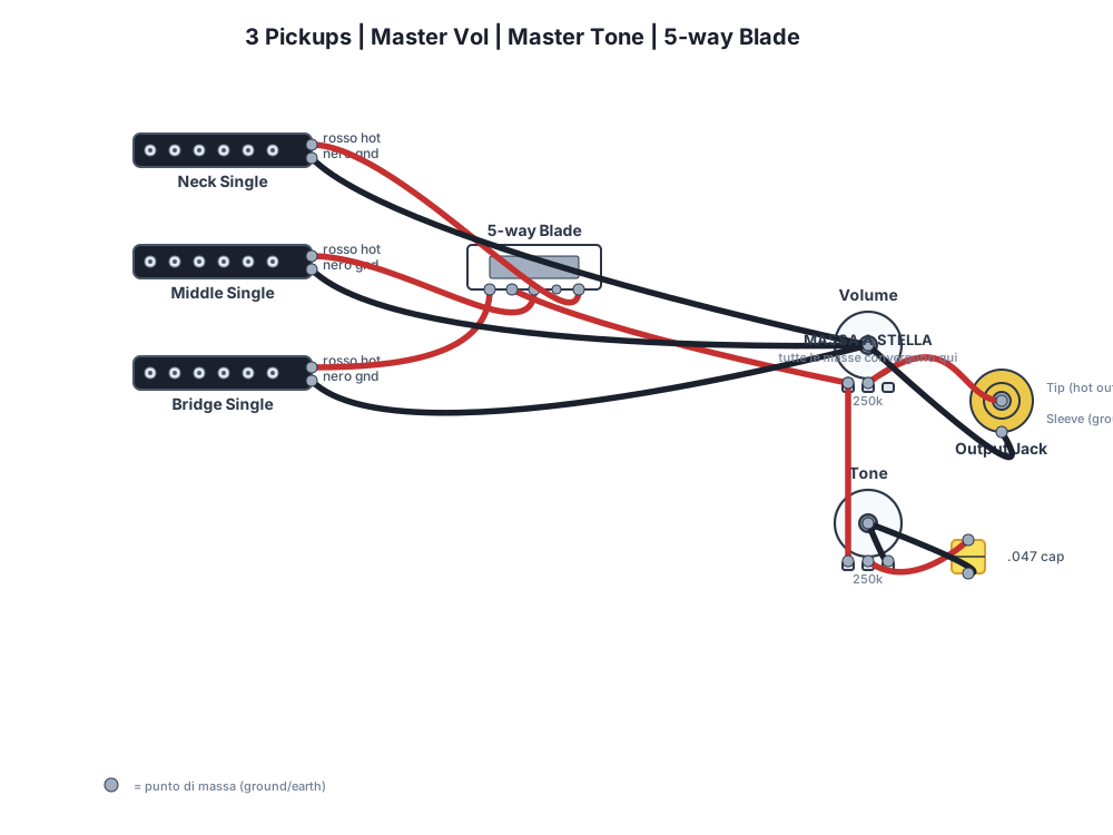
Download the schematic in SVG format and use it as a reference while soldering. The star ground is the central point: all ground wires must converge there.
How to read the diagram
The circuit requires three passive pickups, a master volume potentiometer from 250k or 500k logarithmic, a master tone potentiometer from 250k or 500k logarithmic or linear, a capacitor from 0.022uF or 0.047uF and a 5-way lever selector. The hot wires of the three pickups are soldered respectively to input terminals 1, 2 and 3 of the 5-way selector. The common output of the switch is connected to Terminal 1 of the Master Volume. The Tone potentiometer is connected by connecting its Terminal 1 to Terminal 1 of the Volume. The capacitor is positioned between Terminal 2 of the Tone and the casing of the same tone potentiometer.
Let's analyze for a moment the “why” behind these connections, so you don't just copy a diagram, but understand what you're doing.
THE pick-up generate a very weak signal, which is then amplified. Each pickup has a “hot” wire that carries the signal and a “ground” wire that serves as a reference.
The 5-way selector (or switch) is your orchestra conductor. It allows you to choose which pickup, or combination of pickups, to send to the rest of the circuit. Each switch position closes a specific contact, directing the chosen signal.
The Master Volume potentiometer controls the intensity of the signal output from the guitar. Being a “master”, it acts on all selected pickups. A logarithmic potentiometer (or audio taper) is preferable because the human ear perceives volume non-linearly, and this type of potentiometer offers a more gradual and musical progression.
The Master Tone potentiometer, on the other hand, is a filter. It works in combination with the capacitor to cut higher frequencies, making the sound darker. This is also “master”, so it influences the tone of all selected pickups.
The capacitor is the true heart of tone control. Without it, the potentiometer would do nothing. Its capacitance (expressed in microfarads, uF) determines how many high frequencies are diverted to ground. A higher value cuts more highs, making the sound more “muffled” or “jazz”.
Finally, the star ground is a technique to reduce hum. Instead of connecting all grounds in a loop (which can create “ground loops”), they are all converged to a single central point. It's like an intersection where all ground wires meet and then proceed together towards the output jack.
Essential Components: The Heart of Your Sound
Understanding the components is like knowing the ingredients of a recipe: it allows you to experiment and customize. Let's see in detail what's behind each piece of your master volume and tone circuit.
Passive Pickups
Pickups are the microphones of your guitar. They transform string vibrations into an electrical signal. They are “passive” because they do not require external power. For more information on different types, you can consult resources such as those from Seymour Duncan. There are mainly two types:
- Single-coil: Like those of a Stratocaster. They have a bright and defined sound, but can be subject to hum.
- Humbucker: Typical of Les Pauls. They are two single-coils wired out of phase to cancel hum (“hum-bucking”). They have a fuller sound and higher output.
In our diagram, you have three pickups, usually single-coil for a Strat-type setup, but you could also have different combinations. It is essential to identify the “hot” wire (signal) and the “ground” wire (mass) of each pickup, often indicated by the manufacturer with different colors.
Potentiometers (Pots)
Potentiometers are variable resistors. Turning the knob changes the resistance and consequently the signal flow. The most common values for electric guitars are 250kΩ and 500kΩ.
- Value (250kΩ, 500kΩ): The potentiometer value affects the brightness of the sound. A 250kΩ potentiometer “dumps” more high frequencies to ground, making the sound slightly darker, typical of single-coils. A 500kΩ lets more high frequencies pass, ideal for humbuckers which tend to be darker.
- Logarithmic Curve (Audio Taper): For volume, a logarithmic pot is almost always preferable. This is because our perception of volume is logarithmic, and a logarithmic pot offers a more gradual and natural volume variation throughout the knob's travel.
- Linear Curve (Linear Taper): For tone, you can use either a logarithmic or linear pot. A linear one offers a more direct progression, which can be useful if you want very precise control over the point where the tone starts to darken. Personally, for tone, I often use a linear one, but it's a matter of taste.
Capacitors (Caps)
The capacitor is a passive component that stores electrical energy. In the tone circuit, it acts as a high-pass filter, diverting high frequencies to ground when the tone potentiometer is lowered. Common values are 0.022uF and 0.047uF.
- Value (0.022uF, 0.047uF): A 0.022uF is very common for guitars with humbuckers or for those who want a sweeter tone cut. A 0.047uF cuts more high frequencies, making the sound darker, and is often used with single-coils. The choice is very personal and depends on the sound you are looking for.
- Type: Various types exist, such as ceramic, polyester (Mylar), or “paper-in-oil” (PIO). PIOs are often considered the best for their “vintage” response, but the sonic difference is often subtle and debated. To start, a good polyester capacitor is perfectly fine.
5-Way Lever Selector
This switch is the heart of your pickup selection. It allows you to combine pickups in different ways. The 5 typical positions (as in a Strat) are:
- Neck pickup
- Neck + Middle
- Middle
- Middle + Bridge
- Bridge
Each position closes a specific circuit, sending the signal of the selected pickups to the volume potentiometer.
Output Jack
The jack is where you connect your guitar cable to the amplifier. For electric guitars, a 1/4-inch mono jack is almost always used. It has two contacts: one for the “hot” signal and one for ground. It is crucial that these are soldered correctly to avoid interruptions or hum.
Wires and Soldering
Do not underestimate the importance of good quality cables and well-made solders. Shielded cables reduce interference, and “cold” (poorly made) solders are the number one cause of problems and hums. Patience and precision here pay off.
Tools and Materials: Your Workshop in the Garage
To tackle wiring, you don't need a space lab, but having the right tools makes the difference between a job well done and endless frustration. Here's the essential stuff I always keep handy.
Soldering Iron
don't skimp on quality. A temperature-controlled soldering iron (between 30W and 60W) is ideal. It allows you to work with precision without overheating the components. I use a soldering station that allows me to adjust the temperature, usually between 350°C and 380°C. A clean and thin tip is essential for precise soldering.
Soldering Tin
Use good quality solder, preferably with a flux core. The diameter of 0.6mm or 0.8mm is perfect for guitar electronics. Avoid lead-free solder if you can, it's harder for beginners to use and the aesthetic result isn't always the best, even if it's better for the environment. For hobbies, 60/40 or 63/37 leaded solder is easier to manage.
Desoldering Pump or Desoldering Braid
Mistakes happen. These tools allow you to remove excess solder or correct a wrong solder joint. The pump sucks up molten solder, the braid absorbs it by capillarity. I prefer the braid for precision work.
Pliers, Wire cutters, Wire strippers
Essential for cutting and stripping cables. A good wire stripper with different sizes will save you time and prevent you from damaging the internal wires. Thin-nose pliers are perfect for bending component terminals.
Digital Multimeter
Your best friend for troubleshooting. It allows you to check continuity (if a circuit is closed), the resistance of potentiometers and the polarity of pickups. Never start soldering without first checking the continuity of the ground wires and the jack.
Gloves and Protective Glasses
Safety first. Molten solder can splash, and solder fumes are not good for you. A pair of glasses and thin gloves will protect you without hindering dexterity.
Soldering Support (Third Hand)
A small accessory with two alligator clips and a magnifying glass. It holds the components steady while you solder, freeing up a hand. It's a minimal investment that will save you a lot of frustration.
Insulating or Heat Shrink Tape
To insulate connections and prevent short circuits. Heat shrink is cleaner and more professional, but electrical tape is perfectly fine to start with.
Damp Cloth or Sponge for Tip Cleaning
Always keep the tip of the soldering iron clean. A dirty tip does not transfer heat well and makes soldering difficult and ugly.
Practical steps
Now that we have seen the components and tools, let's get into the heart of the wiring 3 pickup master volume and master tone. Follow these steps calmly, one step at a time. Remember, haste is the enemy of perfect welds.
- Prepare the components and check the values: First of all, take out all your components. Check the potentiometer values with the multimeter (they should be close to 250k or 500k) and the continuity of the selector. Make sure you have the correct capacitor value (0.022uF, 0.047uF or whatever you chose).
- Prepare the cables: Carefully strip the ends of the pickup wires and other wires you will use. Leave exposed only the amount of copper needed for soldering. "Tin" the cable tips: apply a little molten solder to the stripped ends to make them stiffer and easier to solder, and to prevent oxidation.
- Solder the hot wires of the pickups to the selector: Locate the "hot" wires of your pickups (neck, middle, bridge). Connect the hot wire of the neck pickup to input terminal 1 of the 5-way selector. Do the same for the middle pickup (terminal 2) and the bridge pickup (terminal 3). Make sure each solder joint is solid and shiny.
- Connect the selector output to the Master Volume potentiometer: Find the common output terminal of the selector (often labeled "output" or "common"). Solder a wire from this terminal to Terminal 1 (the leftmost one when looking at the potentiometer from the back with the terminals facing up) of the Master Volume potentiometer.
- Connect the Master Volume potentiometer to the Jack: Terminal 2 (center) of the Master Volume potentiometer is the signal output. Solder a wire from here to the "hot" terminal (the longer one) of the output jack. Terminal 3 (the rightmost one) of the Master Volume potentiometer should be soldered to its casing (ground).
- Connect the Master Tone potentiometer: Solder Terminal 1 of the Master Tone potentiometer to Terminal 1 of the Master Volume potentiometer. This puts it in parallel with the main signal.
- Install the Tone capacitor: Solder one end of the capacitor to Terminal 2 (center) of the Master Tone potentiometer. Solder the other end of the capacitor to the casing of the Master Tone potentiometer. This creates the tone filter circuit.
- Connect all grounds to the star point: This is crucial for reducing hum. Locate a central point, often on the casing of one of the potentiometers or on a dedicated point on the shielding. Connect to this point:
- All pickup ground wires.
- The selector ground.
- The casings of both potentiometers (Volume and Tone).
- The ground terminal (the shorter one) of the output jack.
- The wire that goes to the bridge (bridge ground).
- Check continuity with a multimeter: Before closing everything, use the multimeter to check that all grounds are effectively connected to each other and to the ground terminal of the jack. Also check that there are no short circuits between the "hot" signal and ground.
- Test the instrument: Connect the guitar to the amplifier. Test all selector positions, volume and tone potentiometers. Listen carefully for hum, weak sounds, or interruptions.
Tips to avoid buzzing
Hum is the number one enemy of every guitarist. Often, it's not a problem with faulty pickups, but with poor wiring or insufficient shielding. Avoid ground loop: if the potentiometers rest on a common metal shield, do not solder ground wires between their casings. Use an open "C" or "horseshoe" path and bring each ground to the star center. This prevents ground current from circulating in a loop, generating noise. Another thing I learned the hard way is the importance of good internal shielding of the electronics cavity. A well-grounded copper or aluminum foil can work wonders.
To learn more about modifications, also read the guitar modification guide.
Test and Troubleshooting: When Something Goes Wrong
I spent hours and hours looking for the "why" behind a persistent hum or a dead pickup. It's normal for something not to work on the first try, especially the first few times. The important thing is not to get discouraged and to have a method.
Continuity Test with the Multimeter
This is the first, fundamental step after soldering. Set the multimeter to the "continuity" function (often indicated by a diode symbol or a speaker, it beeps if there is continuity).
- Check the ground: Touch the casing of a potentiometer with one multimeter probe and the ground terminal of the output jack with the other probe. It should beep. Do the same with the casings of all potentiometers, the bridge ground, and the pickup ground wires (if accessible). If there is no continuity, you have a disconnected ground.
- Check the "hot" signal: With the volume at maximum and the tone at maximum, touch the "hot" terminal of the jack with one probe and the "hot" terminal of each pickup (if accessible) with the other probe. There should be continuity when the pickup is selected.
- Look for short circuits: Check that there is no continuity between the "hot" signal and ground. If there is, it means a "hot" wire is touching ground somewhere.
Functional Test: To the Amplifier
Connect the guitar to the amplifier and turn it on at a low volume. Then:
- Volume and Tone: Test the volume and tone potentiometers. They should operate smoothly throughout their range, without "holes" or jumps.
- Pickup Selector: Test all selector positions. Each position should activate the correct pickups and produce sound.
- Hum: Listen for any hum or strange noises. A slight hum is normal with single-coils, but if it's excessive or only appears in certain positions, there's a problem.
Common Problems and Solutions
- No Sound:
- Cause: Jack disconnected or poorly soldered, "hot" wire detached from the pickup, selector or volume, ground disconnected.
- Solution: Check all solder joints on the signal and ground path. Use the multimeter to check for continuity.
- Weak or Thin Sound:
- Cause: Out-of-phase pickup (if you tried to reverse its polarity), faulty or wrong value potentiometer (too low), shorted tone capacitor.
- Solution: Check the potentiometer values. If you reversed the phase of a pickup, re-solder it correctly.
- Excessive Hum or Strange Noises:
- Cause: Disconnected ground or ground loop, insufficient shielding, cold (poorly made) solder joints, unshielded or damaged cables.
- Solution: Review all ground solder joints, ensure the star ground is well made and all components are connected. Check the cavity shielding.
- Non-Functioning Controls (Volume or Tone):
- Cause: Faulty potentiometer, disconnected or shorted tone capacitor, cold solder joint on the potentiometer.
- Solution: Check the potentiometer with the multimeter. Check the solder joints of the capacitor and the tone potentiometer.
Once I had a hum that I just couldn't figure out. I disassembled and reassembled everything three times. In the end, I discovered that a tiny piece of solder had fallen and was making contact between two terminals that shouldn't touch. Just a speck! Your eyes and patience are your best friends.
Customization and Variations: Your Unique Sound
This diagram is a great starting point, but the beauty of DIY is that you can modify it to suit your taste. Here are some ideas to customize your guitar wiring diagram.
Capacitor Values
As mentioned, the tone capacitor is crucial. Try experimenting with different values:
- 0.015uF: Less aggressive in treble cut, maintains a bit more brightness even with the tone fully closed.
- 0.033uF: A good compromise between 0.022uF and 0.047uF, it offers a more pronounced cut than 0.022uF without being too dark.
- “No-load” tone pot: Some tone potentiometers have a “no-load” position which, when the pot is at 10, completely excludes the capacitor from the circuit, offering the maximum possible brightness.
Changing the capacitor is one of the simplest modifications with the greatest impact on the tone's sound.
Potentiometer Values
Potentiometers can also be varied:
- Mix of 250kΩ and 500kΩ: If you have a combination of pickups (e.g., single-coil at the neck and middle, humbucker at the bridge), you might want to use a 500kΩ volume potentiometer and a 250kΩ tone, or vice versa, depending on the balance you are looking for.
- 1MΩ Potentiometers: Rarely used, but they can give an extremely bright sound, almost “too much” for some. They increase the circuit's impedance, allowing even more high frequencies to pass through.
Remember that the potentiometer's value “loads” the pickup. A higher value (e.g., 500k) loads the pickup less, leaving it brighter and with a slightly higher perceived output. A lower value (e.g., 250k) loads it more, slightly dampening the highs.
Various Pickups
You are not tied to just one type of pickup. You can combine a bridge humbucker with two single-coils, or use pickups with different outputs. The important thing is to balance the volumes and tones to achieve a consistent sound across different selections.
If you mix pickups from different manufacturers, pay attention to polarity. Sometimes, the “hot” and “ground” wires can be reversed compared to another manufacturer's standard, causing phase problems and a weak or “thin” sound when pickups are combined.
Push-Pull Pots for Extra Functionality
If you want to go further, you could replace one of the potentiometers (volume or tone) with a push-pull potentiometer. These have a small integrated switch that activates by pulling or pushing the knob. With a push-pull pot, you could:
- Split coil: Transform a humbucker into a single-coil.
- Phase switch: Inverting the phase of a pickup for “out of phase” sounds.
- Kill switch: A switch to completely mute the signal.
These modifications add versatility but also complexity to the wiring. To start, the basic diagram is perfect, but it's good to know that the possibilities are endless.
FAQ
Which potentiometers should I use?
It depends on the pickup: single-coil generally 250k, humbucker 500k, active 25k. The choice affects the brightness of the sound and the pickup's “load”. For this universal diagram, 250k is a good base for single-coils, 500k for humbuckers.
Can I use a different capacitor?
Yes, but the value changes the tone's cutoff frequency. Higher = darker sound. A 0.022uF is standard, a 0.047uF cuts more highs, a 0.015uF cuts less. Experiment to find your sound.
Does the quality of the components really matter?
Yes, absolutely. Higher quality components (CTS or Alpha potentiometers, Orange Drop or PIO capacitors, Switchcraft or CRL selectors) ensure greater reliability, better durability, and better interaction with your signal. You might not notice abysmal differences in tone between a 1€ capacitor and a 10€ one, but the smoothness of the potentiometer or the solidity of the switch make a difference in the user experience and the longevity of your wiring.
Is it difficult for a beginner?
It's not impossible, but it requires patience and attention. If you have a minimum of manual skill and carefully follow the diagram, paying attention to the solders, you can do it. Start with inexpensive components to practice and don't be afraid to make mistakes: it's the best way to learn.
I hope this guide has taken away some of your fear and given you the confidence to get your hands on your guitar. Building and modifying electronics is one of the most rewarding experiences in the world of DIY lutherie. It allows you to truly understand how your instrument works and to shape the sound exactly as you want it. Good luck with your next project!
Wiring diagrams library
No diagrams found.
Download the Luthier Survival Kit
Free PDF with checklist, problem-cause table and project card template.
 English
  Italiano
Stuck on your build?
If you ran into the same problem or have a question, drop it in the comments. I read and reply to every one.
Write a comment