
Guitar Electrical Components: 5 Mistakes to Avoid
Have you ever spent hours wiring your latest creation, closed the body with the satisfaction of a child who has just built his first Lego, plugged in the amplifier and... silence? Or a buzz that makes you want to throw the guitar From the window? Yes, I've been there too. Many, too many times. And every time the fault was almost always there, in those small, sneaky ones. electric guitar components which seem harmless but can ruin everything.
I'm not a luthier with a degree in electronic engineering, let's be clear. I'm someone who learned by burning potentiometers, making solder joints that looked like abstract sculptures, and reopening bodies for the tenth time. But precisely because of this, I've understood where the real dangers lie for those like me who build and modify in the garage. I'll tell you right away that it's not something for scientists, but it does require attention and a pinch of method.
In this article, I'll share five common mistakes I've made (and seen others make) with the electronics of the guitar. The idea is simple: if you know where you're going wrong, you can avoid it. And if I managed to do it, with my questionable manual skill and my less-than-iron patience, you can too.
1. Underestimating the Quality of Components (and the Risks of “Too Cheap”)
.biafax-photo-grid { display: grid !important; gap: 12px; margin: 24px 0; }
.biafax-photo-grid-3v { grid-template-columns: repeat(3, 1fr) !important; }
.biafax-photo-grid-2h { grid-template-columns: repeat(2, 1fr) !important; }
.biafax-photo-grid a { display: block; overflow: hidden; border-radius: 6px; line-height: 0; }
.biafax-photo-grid img { width: 100%; height: 100%; object-fit: cover; aspect ratio: 4 / 3; transition: transform 0.3s ease; }
.biafax-photo-grid a:hover img { transform: scale(1.03); }
.biafax-photo-grid br { display: none; }
.biafax-photo-grid-caption { text-align: center; font-style: italic; color: #555; margin: -12px 0 24px; }
.biafax-lightbox-overlay { position: fixed; inset: 0; background: rgba(0,0,0,0.92); display: flex; align-items: center; justify-content: center; z-index: 99999; cursor: zoom-out; }
.biafax-lightbox-overlay img { max-width: 92vw; max-height: 92vh; object-fit: contain; border-radius: 4px; }
@media (max-width: 768px) {
.biafax-photo-grid-3v { grid-template-columns: 1fr !important; }
.biafax-photo-grid-2h { grid-template-columns: 1fr !important; }
}
(function() {
if (window.biafaxGridLightbox) return;
window.biafaxGridLightbox = true;
document.addEventListener(‘click’, function(e) {
var a = e.target.closest(‘a[data-lightbox]’);
if (!a) return;
e.preventDefault();
var overlay = document.createElement(‘div’);
overlay.className = 'biafax-lightbox-overlay';
overlay.innerHTML = '‘‘';
document.body.appendChild(overlay);
overlay.addEventListener(‘click’, function() { overlay.remove(); });
document.addEventListener(‘keydown’, function handler(ev) {
if (ev.key === 'Escape') { overlay.remove(); document.removeEventListener('keydown', handler); }
});
});
})();
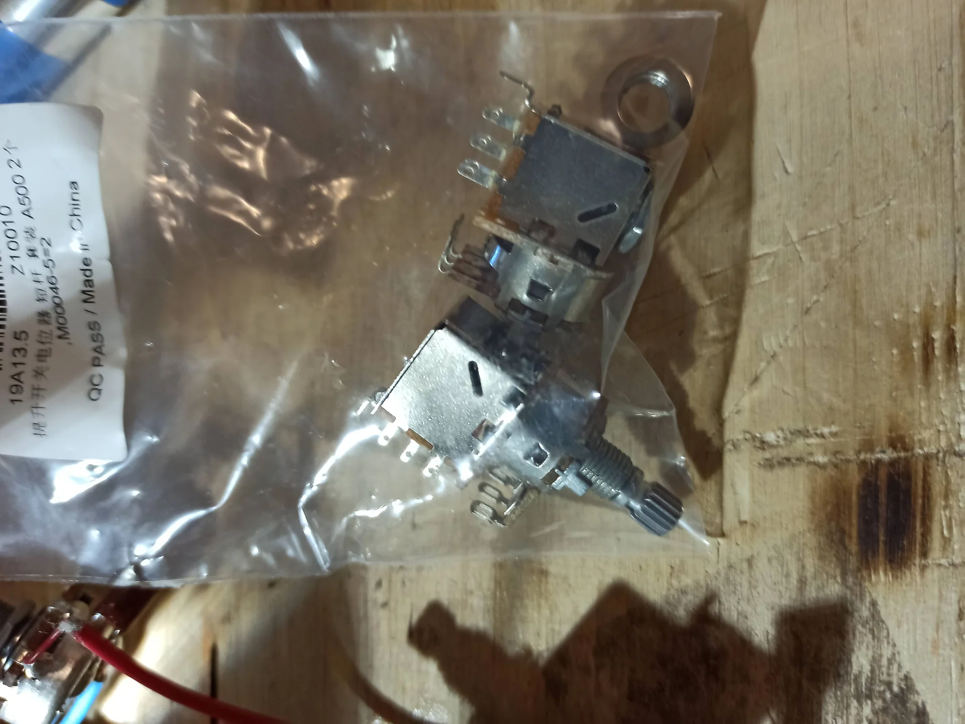
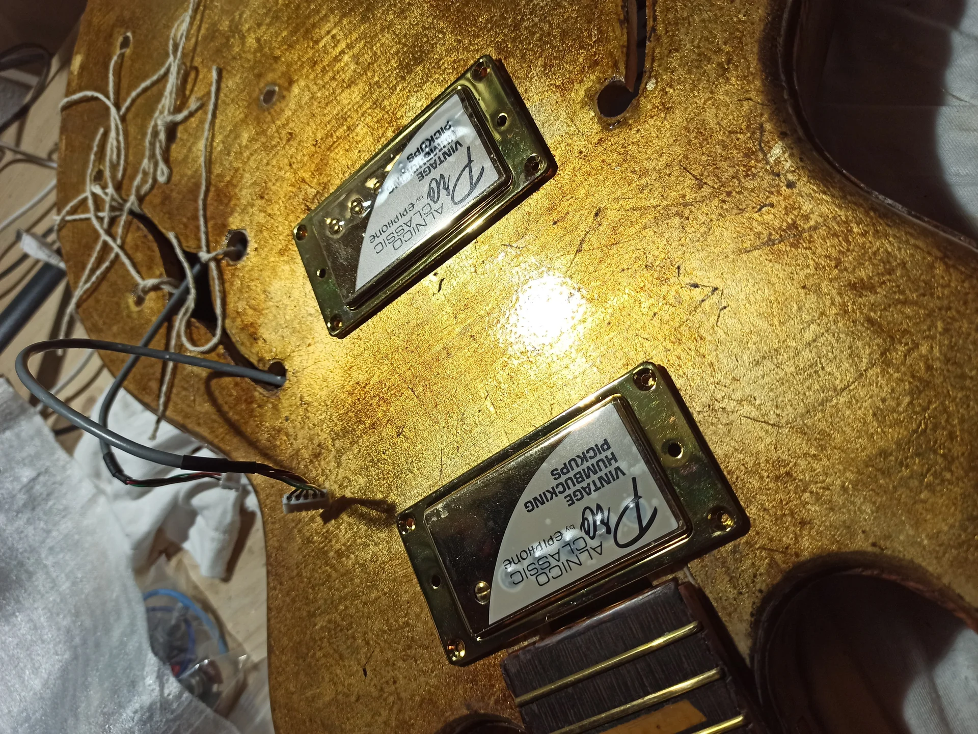
In this gallery: installation, pickups, potentiometers, es339 and wiring.
.biafax-photo-grid { display: grid !important; gap: 12px; margin: 24px 0; }
.biafax-photo-grid-3v { grid-template-columns: repeat(3, 1fr) !important; }
.biafax-photo-grid-2h { grid-template-columns: repeat(2, 1fr) !important; }
.biafax-photo-grid a { display: block; overflow: hidden; border-radius: 6px; line-height: 0; }
.biafax-photo-grid img { width: 100%; height: 100%; object-fit: cover; aspect ratio: 4 / 3; transition: transform 0.3s ease; }
.biafax-photo-grid a:hover img { transform: scale(1.03); }
.biafax-photo-grid br { display: none; }
.biafax-photo-grid-caption { text-align: center; font-style: italic; color: #555; margin: -12px 0 24px; }
.biafax-lightbox-overlay { position: fixed; inset: 0; background: rgba(0,0,0,0.92); display: flex; align-items: center; justify-content: center; z-index: 99999; cursor: zoom-out; }
.biafax-lightbox-overlay img { max-width: 92vw; max-height: 92vh; object-fit: contain; border-radius: 4px; }
@media (max-width: 768px) {
.biafax-photo-grid-3v { grid-template-columns: 1fr !important; }
.biafax-photo-grid-2h { grid-template-columns: 1fr !important; }
}
(function() {
if (window.biafaxGridLightbox) return;
window.biafaxGridLightbox = true;
document.addEventListener(‘click’, function(e) {
var a = e.target.closest(‘a[data-lightbox]’);
if (!a) return;
e.preventDefault();
var overlay = document.createElement(‘div’);
overlay.className = 'biafax-lightbox-overlay';
overlay.innerHTML = '‘‘';
document.body.appendChild(overlay);
overlay.addEventListener(‘click’, function() { overlay.remove(); });
document.addEventListener(‘keydown’, function handler(ev) {
if (ev.key === 'Escape') { overlay.remove(); document.removeEventListener('keydown', handler); }
});
});
})();
Ah, soldering! The terror of many, the joy and bane of DIY. My first solder joints looked like sticky solder balls, or lunar craters. They weren't joints, they were attempts at nuclear fusion. And of course, the sound was a disaster. Intermittent, noisy, nonexistent.
A poorly made solder joint is like an obstacle in the way of your signal. It can create unwanted resistance, noise, or even completely interrupt the flow. It's one of the main reasons why an electrical project fails.
The right tools: don't improvise
You don't need a space lab, but you do need a decent soldering iron.
Welder: A temperature-controlled soldering iron is ideal, but a 25-40W fine-tipped iron is also fine for most guitar work. The tip must be clean and tinned (with a thin layer of solder). A oxidized tip will not transfer heat well.
Pond: Use good-quality solder with a flux core (usually 60/40 tin/lead or lead-free solders specifically designed for electronics). The flux helps the solder flow and form a good joint. Avoid thick flux; you'll need a thinner diameter (0.5-0.8 mm) for precision work.
Accessories: A soldering iron stand, a damp sponge to clean the tip, a fume extractor (essential for your health!), and perhaps some small pliers or “third hand” clamps to hold the wires.
Welding technique: a question of heat and timing
The goal is to create a solid, shiny, cone-shaped (or “volcano”) electrical and mechanical junction.
1. Clean Terminals: Make sure the wires and component terminals are clean and free of oxide. If necessary, scrape them gently with a razor blade or use a little flux.n2. Prepare the Cables: Strip the wires to the required length (usually a few millimeters) and twist the copper wires tightly. If possible, lightly pre-tin both the wire and the component terminal. 3. Apply Heat: Rest the tip of the soldering iron at the same time on the component terminal and on the wire you need to solder. The idea is to heat both.n4. Apply Tin: After 1-2 seconds, bring the pond closer at the point of contact between the wire and the terminal, not at the tip of the soldering iron. The solder should melt on the workpiece, not at the tip.n5. Remove Tin and Soldering Iron: As soon as you see the solder flow and form a nice, shiny joint, remove the solder first, then the soldering iron. Leave the joint alone for a few seconds until it cools.
Common Mistakes to Avoid:
Cold Joints: They appear dull, lumpy, and lack lustre. They are caused by insufficient heat or by the component moving during cooling. They are the primary cause of intermittent problems.
Overheating: Excessive heat or too much time can damage components (especially potentiometers and switches) or melt the wire insulation. Be quick and efficient.
Short circuits: Too much solder, or solder leaking where it shouldn't, can create bridges between different terminals, causing short circuits. Always check carefully!
My advice: Practice. Take an old circuit board, or even just some wires and terminals, and solder. Fail. Redo. Watch tutorials on YouTube. The good news is that guitar soldering isn't microelectronics stuff, but it's crucial to do it right. Good solder is shiny, smooth, and mechanically bonded.
3. Ignoring Shielding and Cable Management
Have you ever had a guitar that sounds great, but then, when you're not touching it, it emits an annoying buzz? Or that picks up the neighbor's radio (yes, it happened to me!)? Well, you almost certainly have a shielding or wiring problem. This is a mistake I've made again and again, thinking it was "just a minor detail." Instead, it's crucial for a clean sound.
Electric guitars, especially single-coil ones, are highly susceptible to electromagnetic interference (EMI) and radio frequency interference (RFI). Shielding creates a "Faraday cage" around the electronics, diverting this unwanted noise to ground.
Why shielding is important
Think of your guitar's electronics as a small antenna. It picks up unwanted signals from your surroundings: fluorescent lights, computer monitors, Wi-Fi routers, even your amplifier. These signals translate into hum, hiss, and background noise. Good shielding dramatically reduces this problem.
How to screen properly
There are two main ways to shield guitar cavities:
1. Copper Foil Tape: This is my favorite method. It's easy to apply, conductive, and long-lasting. You need to cover all the internal walls of the cavities (pickups, controls, jacks) with the tape, making sure each piece overlaps the previous one to ensure electrical continuity. It's essential that all the tape is grounded. 2. Conductive Paint: A graphite or nickel-based paint that, once dry, becomes conductive. It should be sprayed or brushed onto all cavity walls. Again, it's crucial to ensure the paint is grounded.
Key Steps for Shielding:
Cover Everything: The pickup and control cavities must be completely covered. Do not leave any holes.
Continuity: Each piece of tape or layer of paint must be in electrical contact with the others and, most importantly, with the circuit's ground. You can use a small piece of tape to connect the cavity walls to the back of a potentiometer (which is grounded).
Grounding: Make sure all non-signal metal components (bridges, strings, tuners, shielding) are grounded. A good star ground point (where all ground wires converge at a single point) is ideal for minimizing ground loops that can cause noise.
Head: Using a multimeter, check the continuity between the various shielding points and the circuit ground. If there is no continuity, there is no shielding.
Cable Management: Order and Cleanliness
It's not just a matter of aesthetics. The way the cables are laid out inside the guitar affects the noise.
Shorten the Cables: Use cables as short as possible. Every inch of cable is a potential antenna.
Avoid Unnecessary Crossroads: Try not to cross signal wires with power wires (if any, as in some active circuits) or with other wires that could introduce noise. If you must cross them, do so at a right angle to minimize coupling.
Shielded Cables: The cables carrying the signal from the pickups to the potentiometers should be shielded. This further reduces the possibility of interference. They usually have two conductors: one for the signal (the "hot" conductor) and one for ground (the outer shield).
A common misconception is that shielding is only for cheaper guitars. This is false. Even high-end guitars benefit from good shielding.
My advice: Spend time on shielding and wiring. It's not as sexy as installing a new pickup, but I assure you, the difference in terms of clarity of sound is huge. If you want to learn more about how shielding can transform your guitar's tone, check out our guide on how to modify your guitar, where we also talk about measures to minimize noise.
4. Getting the Values or Wiring Diagrams Wrong
How many times have I heard: “I followed a pattern, but it doesn't sound as it should!” Or: “I mounted my new pickups, but the sound is muddy.” In most cases, the fault is not the pickups, but an error in the values of the electrical components or in a misreading of the wiring diagram.
Each pickup has specific characteristics and requires a certain electronic "interface" to perform at its best. You can't randomly add potentiometers and capacitors and expect everything to sound good.
Potentiometer Resistance: The Right Match
We have already mentioned values, but this is such a crucial mistake that it deserves to be reiterated.
Single Coil: Almost always, 250kΩ is used for volume and tone. This value allows single-coil pickups, which tend to be brighter and sharper, to have a more balanced sound, slightly rolling off the higher frequencies. If you were to use 500kΩ with very bright single-coil pickups, you might end up with a sound that's too bright and thin.
Humbucker: Generally, 500kΩ is used for volume and tone. Humbuckers are more powerful and have a fuller frequency response, with less highs. The 500kΩ allows them to open up more, maintaining brightness and definition. If you used 250kΩ with humbuckers, the sound would be darker, less defined, and often muddy, as if your tone was always in the middle.
P90 or vintage humbucker/bass output: Sometimes 300kΩ or even 250kΩ are used, depending on the desired sound. It's a matter of experimentation and personal taste, but always starting from a logical basis.
My advice: Always check the specifications of your pickup manufacturer. They know which potentiometer settings are best for their products. Don't guess.
Tone Capacitors: Shaping the Sound
Again, the capacitor value is critical to how the tone control will affect the sound.
Single Coil: Standard 0.047uF. This value allows for a significant cut in high frequencies, useful for obtaining softer, jazzier sounds.
Humbucker: Standard 0.022uF. With humbuckers, which are already less bright than single coils, a lower value allows for a less aggressive high-end cut, maintaining good definition even with the tone at zero.
Experimentation: This is an area where you can experiment. Want a darker sound? Try a higher-value capacitor. Want a less drastic cut? Try a lower value. But always start with the standard values as a reference.
Wiring Diagrams: The Treasure (or Disaster) Map
Wiring diagrams are your guide. Ignoring them or misreading them is a huge mistake.
Find Reliable Schemes: Don't take the first diagram you find on Google Images. Trust the websites of the pickup manufacturers (Seymour Duncan, DiMarzio, EMG, Fender) or reputable resources like guitarelectronics.com. They are clear, tested, and reliable. For example, the Seymour Duncan wiring diagrams They are a fantastic and well-organized resource.
Read carefully: Each manufacturer uses different colors for their pickup wires. A red wire for a Seymour Duncan might be a green wire for a DiMarzio. Make sure you know exactly what each color represents. your pick-up.
Mass Points: Pay attention to ground points. All metal components that need to be grounded (back of potentiometers, bridge, shield) must be connected. A ground fault can cause noise or no signal.
Special Configurations: Coil split, phase switching, series/parallel… If you're doing something more complex than standard wiring, schematics are even more important. Follow each step with a finger, one at a time.
My advice: Don't rush. Print the diagram. Check each connection as you make it. Use a highlighter to mark the connections you've already made. And if you have any doubts, look for an explanation or a video tutorial specific to that type of wiring. Remember, wiring is the electronic configuration of your guitar: a small mistake here compromises the whole sound.
5. Lack of Patience and Thorough Testing
This is perhaps the most human mistake, and the one that has caused me the most frustration of all. The rush to finish, the desire to hear the guitar play right away, and boom: you close everything, plug it in, and discover that the tone pot isn't working, or that there's a buzz that wasn't there before. And you have to reopen everything. Remove the strings, remove the pickguard, maybe unsolder a few wires. How irritating!
The truth is that the assembly of the electrical components requires patience and a methodical approach to testing. Whenever you work on the electrical circuit of a guitar, it is essential to check the work done before sealing everything.
Continuity Test with Multimeter
A multimeter is your best friend. It's not a scientist's tool; you can find one for just a few euros and it will save you a lot of trouble.
Mass Test: Set the multimeter to continuity mode (the one that beeps). Touch one probe to the ground of the output jack (the long end) and the other to all the points that should be grounded: the back of the potentiometers, the cavity shielding, and the bridge (if connected to ground). Each point should beep. If it doesn't, you have a ground problem.
Signal Test: Set the switch to a position and check the continuity between the hot wire of the selected pickup and the hot post of the output jack (the tip). Then, with the potentiometers fully opened, check the continuity between the signal terminals.
Potentiometer Test: With the multimeter in resistance mode, check the resistance between the potentiometer terminals as you turn it. You should see the resistance change smoothly. If there is a jump or gap, the potentiometer may be defective or have a cold solder joint.
Bench Testing (or Almost)
Don't close the body without testing the circuit! This is a lesson I learned the hard way.
1. Temporary Assembly: Once you have wired up the entire pickguard/electronics assembly (or the control plate), but Before To permanently mount it in the body, connect it to an amplifier. You can use alligator clips to connect the guitar bridge to the circuit ground.n2. Test Pickup: If you haven't mounted the final pickups yet, you can connect any pickup (even a scrap one) to the circuit terminals to simulate its operation.n3. Functional Check: Touch the