

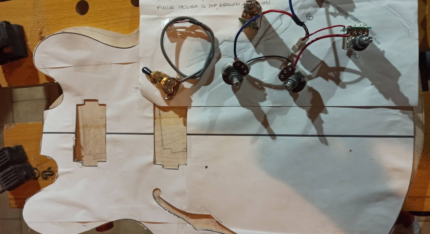
SSS Stratocaster Wiring: Step-by-Step Diagram
When I decided to tackle the wiring of my first Stratocaster, I remember the feeling very well. A mix of excitement for the potential for customization and a touch of terror in front of all those wires, potentiometers, and solders. The Stratocaster SSS, with its three single coils, is an icon, a workhorse for genres ranging from blues to rock, from funk to pop. But its distinctive sound is not just a matter of woods or pickups: it's the electronics, the pulsating heart hidden under the pickguard, that bring those nuances to life. I was there, in my garage, with a soldering iron in hand that looked like an alien weapon and an electrical diagram that at first glance seemed written in hieroglyphs. But the truth is that the guitar wiring, even for an iconic model like the Strat, is not black magic. It's logic, patience, and a bit of practice. If I, who at first could barely distinguish a capacitor from a resistor, managed it, you can do it too. In this article, I will guide you through the process of Stratocaster SSS wiring, one step at a time. Not only will I show you as how to make the connections, but I will also explain why why each component is there and what it does for your sound. The goal is to take away your fear of the soldering iron and the electrical diagram, transforming them into familiar tools to create your ideal sound. Get ready, because we are about to give new life to your Strat.
Essential Components: Knowing the Building Blocks of Your Sound
Before you start soldering, it's essential to understand what you have in your hands. Each component of your Stratocaster SSS circuit has a specific role and contributes uniquely to the final sound. Knowing them will help you not only follow the diagram but also understand how any modifications can influence the tone.
Single Coil Pickups: The Heart of the Strat
THE single coil pickup are the soul of the Stratocaster. They are coils of wire wound around magnets, which transform string vibrations into an electrical signal. The typical single coil sound is bright, clear, and with a good amount of attack. Each pickup usually has two wires: one for the signal (hot) and one for the ground. Sometimes, as in vintage-type Fender pickups, you might find a coated wire that acts as the signal and the outer braid as ground. It is essential to correctly identify these wires to avoid phase or noise problems.
Potentiometers (Pots): Volume and Tone Control
Potentiometers, or “pots”, are variable resistors that allow us to adjust the volume and tone of the guitar. For a Stratocaster SSS, 250kΩ (kilo-ohm) potentiometers are typically used.
Values and Function
250kΩ: This value is the standard for single coil pickups. It offers a good balance, maintaining the brightness of the pickups without making them too harsh. A higher value (e.g., 500kΩ) would let more high frequencies pass through, making single coils a bit too “icy” or sharp for many. A lower value (e.g., 100kΩ) would “soften” the sound too much, cutting many high frequencies. Volume: The volume potentiometer is always placed first in the circuit, after the pickup selector. It adjusts the overall intensity of the signal coming out of the guitar.
Tone: Tone potentiometers work in combination with capacitors to cut high frequencies. The more you lower the tone, the “darker” and less bright the sound becomes.
Taper: Audio (Log) or Linear?
Potentiometers have a “taper”, which is the way the resistance changes as the knob is turned.
Audio Taper (Logarithmic): The resistance changes slowly at the beginning of the travel and more rapidly towards the end. This is ideal for volume, as the human ear perceives volume logarithmically.
Linear Taper (Linear): The resistance changes uniformly throughout the travel. Often used for tone, although many prefer audio taper even for tone controls for greater progressiveness in the initial part of the travel. For a standard Strat SSS, audio taper potentiometers are usually used for volume and tone.
Selector Switch (5-Way Switch): Your Orchestra Conductor
The 5-way switch is the true orchestra conductor of your Stratocaster. It allows you to select pickups individually or in specific combinations, offering a wide range of sounds.
How It Works
Internally, a standard 5-way selector for Stratocaster has two “sides” or “poles” independently, each with a common terminal and five input terminals. When you turn the lever, the internal contacts connect one of the inputs to the respective common.
Position 1 (Bridge): Selects only the bridge pickup.
Position 2 (Bridge + Middle): Combines the bridge and middle pickups (often in parallel and out of electrical phase for hum-cancelling if the middle pickup is reverse polarity).
Position 3 (Middle): Select only the middle pickup.
Position 4 (Middle + Neck): Combines the middle and neck pickups (here too, often hum-cancelling).
Position 5 (Neck): Select only the neck pickup.
The common signal from one of the selector's poles is sent to the volume potentiometer. The other pole can be used for tone controls or more complex wiring schemes.
Capacitors (Caps): The Tone Filters
THE capacitors are passive components that store electrical energy. In a guitar's tone circuit, they act as high-pass filters, allowing only higher frequencies to pass through them to ground, cutting them out of the main signal.
Typical Values
0.022µF (microfarad): This is the most common value for single coil pickups. It offers a balanced high-frequency cut, making the sound warmer without making it excessively muddy. 0.047µF: A higher value will cut more high frequencies, making the sound darker. Some blues guitarists prefer it for softer tones.
Types: There are various types of capacitors (ceramic, polyester, paper/oil, etc.), each with subtle tonal differences. To start, a good polyester capacitor is more than sufficient. In my tests, I noticed that the difference between a “vintage-style” paper/oil capacitor and a good polyester is often more psychological than audible, especially in a live context. But the value is what matters!
Output Jack: The Sound Gate
The output jack is the point where your guitar's signal meets the amplifier. For electric guitars, a 1/4-inch mono jack is used. It has two terminals:
Tip: Here the “hot” signal coming from the volume potentiometer is connected.
Sleeve: Here the general circuit ground is connected.
Wires and Shielding: Conduits and Protection
The internal wires of the guitar carry the signal and the ground. It is important to use good quality wires, preferably multistrand, to facilitate soldering and ensure good conductivity.
The shielding is fundamental for reducing noise and electromagnetic interference (EMI). It is achieved by lining the electronics cavities with conductive paint or copper/aluminum foil, then connecting this shielding to the general ground. Good shielding can make the difference between a clean sound and one full of annoying hums.
Necessary Tools: Your Garage Workshop
You don't need space lab tools, but having the right tools makes the job much simpler and the result better.
Welder: A 25-40W fine-tip soldering iron is ideal. Avoid overly powerful ones that could damage components or thin wires.
Pond: Solder with flux core (preferably lead-free, but leaded is easier for beginners to use).
Wire stripper: To cleanly remove insulation from wires.
Wire cutters: To cut wires and excess solder.
Multimeter (Tester): Essential for checking solder joint continuity, identifying short circuits, and verifying component values. Trust me, it will save your life more times than you think.
Protective Eyewear: Solder splinters and smoke are no joke for the eyes.
Clamps or “Third Hand”: To hold components steady while soldering.
Desoldering pump or desoldering braid: To correct any errors.
Electrical tape or heat shrink tubing: To insulate exposed connections.
With these components and tools, you are ready to dive into the world of wiring your Stratocaster!
Circuit Basics: Grounding and Signal
Before delving into the specific Stratocaster diagram, it is crucial to understand two fundamental concepts of guitar electronics: signal and ground. These two elements are the backbone of every audio circuit, and understanding them will help you diagnose problems and wire with greater awareness.
The Signal (Hot)
The signal, often called “hot” or “positive”, is the part of the circuit where the audio information generated by your pickups travels. It is an alternating current (AC) flow that varies according to string vibrations. This signal, once it leaves the pickups, passes through the potentiometers (volume and tone), the pickup selector, and finally the output jack, to then reach the amplifier. Each pickup has a wire that carries the signal. In diagrams, this wire is often represented in a different color (e.g., white or yellow) to distinguish it from the ground. It is the most important path, the one that carries your sound.
The Ground (Ground)
The ground, or “ground”, is the zero potential reference point for the entire circuit. It is a return path for current and serves two main purposes: 1. Close the Circuit: Current always flows in a closed circuit. The hot signal goes forward and the ground provides the return path. Without a complete ground path, there is no sound. 2. Shielding and Noise Reduction: All metallic components of the guitar (bridge, strings, tuners, cavity shielding) should be connected to ground. This creates a kind of “Faraday cage” that helps deflect electromagnetic interference (EMI) and reduce unwanted hums. Think of it as a safety net that captures and dissipates noise before it can reach the audio signal.
How to Create a Common Ground Point
In a Stratocaster, it is good practice to create a common ground point. This often happens on the back of a potentiometer casing (usually the volume one) or on a dedicated terminal. All ground wires coming from the pickups, potentiometer casings, output jack (sleeve), cavity shielding, and bridge converge at this point.
Ground Continuity: It is essential that every metallic component and every ground wire is securely soldered to this common point or to a path leading to it. A “floating ground” (a component that should be grounded but isn't) is one of the most common causes of hums and noises. Use your multimeter to check continuity between all ground points. There should be a resistance close to zero (or a “beep” if the multimeter has this function) between any ground point and another.
In summary, the signal carries the sound, the ground protects and completes it. Understanding this dynamic will give you a huge advantage in debugging and customizing your circuit.
Standard SSS Wiring: Step by Step
Now that we have familiarized ourselves with the basic components and concepts, it's time to get hands-on and wire your Stratocaster SSS. This diagram is the classic one, which has defined the “Strat sound” for decades.
For this diagram, we will use the most common configuration: a general volume potentiometer, a tone potentiometer for the neck pickup, and another tone potentiometer for the middle pickup. The bridge pickup will be without direct tone control, for a brighter and more aggressive sound.
Conceptual Diagram: Visualizing the Path
Imagine the signal flow:
1. The three pickups send their signal to the 5-way selector.
2. The selector decides which pickup (or combination) to send.
3. The selected signal goes to the volume potentiometer.
4. From the volume potentiometers, the “clean” (or attenuated) signal goes to the output jack.
5. In parallel to the signal path, the tone potentiometers and capacitors take a portion of the signal and divert it to ground, cutting high frequencies.
6. All components (pickups, potentiometers, selector, jack, bridge, shielding) are connected to each other via ground.
Detailed Soldering Steps
For clarity, we will use a common color convention for Fender-style pickups:
Hot wire (signal): Black (or sometimes white)
Ground wire: White (or sometimes black, or the outer braid)
ATTENTION: Always check your pickup manufacturer's specifications, colors may vary! If you are unsure, use a multimeter to identify the wires.
1. Component Preparation and General Grounding
2. Connecting the Pickups to the 5-Way Switch
The 5-way switch has two rows of terminals. For the standard SSS scheme, we will use one row for the pickup inputs and the other for the common output and tones.
3. Connecting the Volume Potentiometer
The volume potentiometer è the first after the switch.
4. Connecting Tone Potentiometers and Capacitors
Now we connect the two tone potentiometers.
Note: Some modern Stratocaster diagrams connect tone 2 to control both the middle and bridge pickups. If you want this option, solder the wire from the switch to tone potentiometer 2 so that it takes the signal from positions 1, 2, and 3 of the switch. For the classic SSS scheme, the bridge remains “wide open” without tone.
5. Connecting the Output Jack
This è the last connection for the signal.
Final Verification and Test
Once all solders have been made:
1. Visual Inspection: Check each solder joint. They should be shiny, cone-shaped, not dull or “cold”. Make sure there are no exposed wires that could touch other components or the shielding, causing short circuits.
2. Continuity Test (Multimeter):
Check for continuity between all ground points (pot casings, switch frame, jack ground, bridge wire). There should be continuity everywhere.
Check that there are no short circuits between signal and ground at any point. For example, between the “tip” of the jack and the “sleeve” there should be no continuity when the volume è at maximum and the tones are open. If there ’è one, you have a short.
3. Functional Test: Connect the guitar to the amplifier.
Test each switch position.
Check the volume potentiometer (it should smoothly increase and decrease the sound).
Check the tone potentiometers (they should progressively darken the sound).
Listen for any hums or unusual noises.
Don't be discouraged if something doesn't work on the first try. È normal! Troubleshooting è an integral part of the process. Recheck your solders, your connections, and your ground.
Alternative Diagrams and Customizations (Overview)
The standard Stratocaster SSS wiring è a fantastic starting point, but the beauty of DIY è the ability to customize the sound according to your needs. Once you've mastered the basic scheme, you might want to explore some common modifications.
Popular Modifications
Treble Bleed: This è a small network (capacitor and/or resistor) soldered between the input and output of the volume potentiometer. Its purpose è to preserve high frequencies when you lower the volume, preventing the sound from becoming too “muddy” or dark. È one of the most appreciated modifications for those who use the volume control on the guitar a lot.
Blender Pot: By replacing one of the tone potentiometers with a “blender pot” (often a push-pull potentiometer or a linear taper potentiometer), you can blend the pickups in unconventional ways. For example, you could add the neck pickup to positions 1 and 2, or the bridge pickup to positions 4 and 5, achieving combinations like neck+bridge or all three pickups together.
Tone for the Bridge Pickup: As mentioned before, many modern Stratocasters connect the second tone to also act on the bridge pickup, or even only on the bridge pickup. This gives you more control over the bright and aggressive sound of the bridge pickup.
Mini-Switch: The addition of mini-switches (on-on, on-off-on) can unlock an infinity of options, such as wiring two pickups in series (for a thicker and more powerful sound, similar to a humbucker), phase inversion (for “out of phase” sounds like Peter Green, but often very nasal), or activating all pickups together.
These are just some of the possibilities. If you want to go further with modifications and customize your instrument even more, take a look at our guide on guitar modifications. There you will find ideas and tips to transform your instrument into something truly unique.
For more complex diagrams or to understand how to connect pickups from different brands, resources like the Seymour Duncan website offer a vast library of detailed diagrams for almost every imaginable configuration. It is an excellent resource for expanding your knowledge. You can consult their diagrams here: Seymour Duncan Wiring Diagrams.’
Remember, every modification è an experiment. Don't be afraid to try, but always back up the original diagram and take notes on your experiments.
Common Problem Solving (Troubleshooting)
Even the most experienced luthiers, or “garage electricians” like me, find themselves having to troubleshoot. È a normal part of the process, and learning to diagnose problems will make you a much more competent wirer. Don't panic if something doesn't work, è an opportunity to learn.
No Sound
This è the most common problem and often the easiest to solve.
Check the Jack: Make sure the cable is fully inserted into the amplifier and the guitar. It seems trivial, but how many times has it happened to me!
Check the Volume: Is the volume potentiometer at maximum? Is it not a faulty “pot”?
Jack Soldering: The solder joints at the output jack are the most stressed. Check that the wires (signal and ground) are well soldered to the “tip” and “sleeve” terminals. A cold or broken solder joint here è a very frequent cause.
General Mass: Is there continuity between all ground points? If the ground wire from the bridge has come off, or if the ground wire from the jack is not connected, you might have no sound or a very loud hum.
Broken or Shorted Wires: Visually check all wires. An internal wire might have broken or the insulation might be damaged, causing a short circuit.
Weak or Distorted Sound
If the sound è present but not as it should be, the problem might be more subtle.
Pickup Polarity: If you have wired a pickup with reverse polarity compared to the others, when combined (selector positions 2 and 4) the sound will be weak, nasal, and “thin”. This è because the sound waves partially cancel each other out. Reverse the hot and ground wires of the offending pickup.
Faulty Potentiometer: A faulty volume or tone potentiometer can cause a weak, intermittent sound or unwanted distortion. Try temporarily bypassing the potentiometers (connecting the signal directly) to see if the problem persists.
Cold Welding: A solder joint that looks good but doesn't conduct well (a “cold solder joint”) can cause a weak and intermittent signal. Redo suspicious solder joints.
Excessive Noise (Hum, Buzz)
Noise is the guitarist's number one enemy.
Incomplete Mass: The most common cause of hums and buzz. Make sure that every metal component (bridge, strings, tuners, pot casings, cavity shielding) is firmly connected to the general ground. Use a multimeter to check continuity.
Insufficient Shielding: If the pickup and electronics cavities are not properly shielded (with conductive paint or copper/aluminum foil) or if the shielding is not grounded, the guitar will be more susceptible to electromagnetic interference.
Cold Solder Joints or Solder Bridges: A solder bridge (a drop of solder accidentally connecting two terminals that should not be connected) can cause a short circuit or an unwanted ground loop, generating noise.
Uninsulated Wires: Make sure all “hot” wires are well insulated and do not touch ground or other wires.
Single Coil Pickup: Remember that single coils are by their nature more susceptible to 50/60Hz hum than humbuckers. The intermediate positions of the Strat (2 and 4) are hum-cancelling if the middle pickup and one of the others are reverse polarity. If you only have noise in positions 1, 3, 5, it's normal for single coils. If you also have it in positions 2 and 4, you might have a phase or grounding problem.
What to Do if It Doesn't Work
1. Breathe Deeply: Frustration is the enemy of clarity. 2. Review the Schema: Compare your work with the scheme multiple times. Don't take anything for granted. 3. Use the Multimeter: It is your best friend. It checks continuity, short circuits, and component values. 4. Welding for Welding: If you don't find the problem, desolder and resolder the connections one by one, checking each time. 5. Ask for Help: If you're stuck, post clear photos of your wiring on online forums dedicated to DIY luthiers. Often an outside eye sees what you don't. Remember, every mistake è a lesson. I've learned much more from my failed wirings than from perfect ones. Patience and perseverance are your most powerful weapons.
Conclusion: Your Sound, Your Hands
At this point, I hope you have lost that initial fear of getting your hands on your guitar’s electronics. The wiring of a Stratocaster SSS, as we have seen, is a logical and rewarding process. It's not just a matter of connecting wires, but of understanding how each component contributes to the final sound, allowing you to consciously shape the timbre of your guitar. Having control over your sound, from the choice of pickups to the value of potentiometers and capacitors, down to the care of the solders, is an invaluable experience. Not only will you have an instrument that sounds exactly how you want it, but you will also have gained a deep understanding of its internal workings. And trust me, that feeling of playing your guitar knowing that you you brought its electronics to life, it's something no store purchase can ever match. Keep experimenting, learning, and having fun with your music.
FAQ
What is the difference between 250k and 500k potentiometers?
250kΩ potentiometers allow fewer high frequencies to pass through compared to 500kΩ ones. For single coil pickups, 250kΩ are the standard because they help to “tame” their brightness, preventing the sound from becoming too harsh or “ice-picky”. 500kΩ are more often used with humbuckers, which tend to be darker and benefit from a greater passage of high frequencies to maintain clarity and definition.
Can I use a capacitor of a different value for the tone?
Absolutely yes! The value of the tone capacitor directly influences how many high frequencies are cut. A 0.022µF capacitor is the standard for the Stratocaster SSS, offering a good balance. If you want a darker and “softer” sound when you lower the tone, you can try a higher value like 0.047µF. If, on the other hand, you want a more subtle and less drastic cut of the highs, a lower value like 0.015µF might be for you. Experimenting with capacitors is a great way to further customize your sound.
Wiring diagrams library
No diagrams found.
Download the Luthier Survival Kit
Free PDF with checklist, problem-cause table and project card template.
 English
  Italiano
Stuck on your build?
If you ran into the same problem or have a question, drop it in the comments. I read and reply to every one.
Write a comment