
How it works electronics guitar? 3 practical diagrams
When I got my hands on my first electric guitar to modify, electronics It seemed like a labyrinth of colored wires and mysterious components. There was a certain awe, let's face it. That tangle under the pickguard? Black magic, I thought. Then I started fiddling, making mistakes, redoing. And I realized it's not magic at all, just common sense and a little basic physics.
If you've ever found yourself staring at a wiring diagram with the expression of someone who's just seen an alien, don't worry: we've all been there. The goal of this article is to help you understand not only as you connect a component, but above all Why it connects that way. Once you understand how guitar electronics work, the wiring It becomes child's play. Or almost.
I'll show you three practical diagrams, starting from the basics and moving on to more complex configurations. I'll give you some tips from a Sunday luthier like me, someone who learned to solder with a cheap soldering iron and burned out a few potentiometers before figuring out the trick. So, grab your soldering iron, multimeter, and a lot of patience: let's start to really understand how it works. electronics of a guitar.
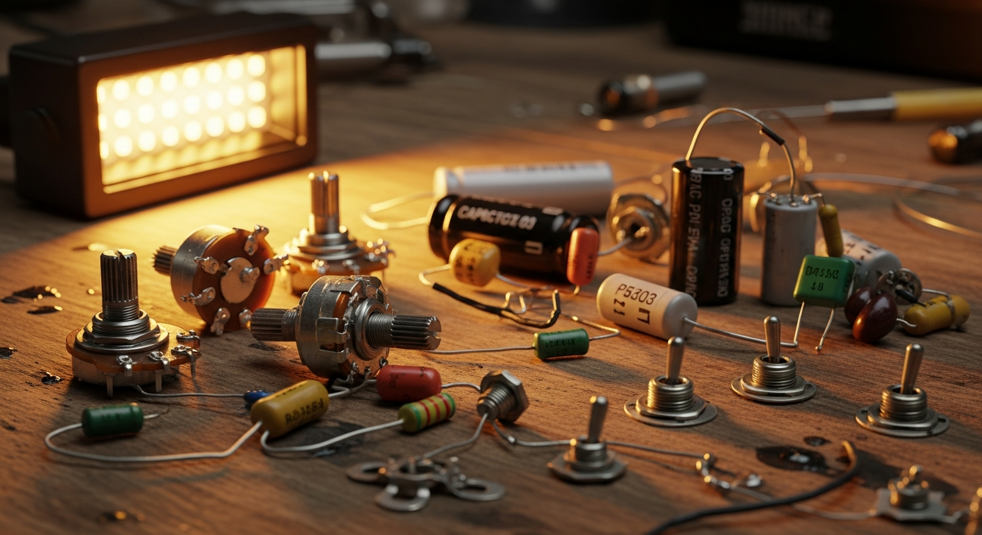
The Basics: The Signal Path and Fundamental Components
.biafax-photo-grid { display: grid !important; gap: 12px; margin: 24px 0; }
.biafax-photo-grid-3v { grid-template-columns: repeat(3, 1fr) !important; }
.biafax-photo-grid-2h { grid-template-columns: repeat(2, 1fr) !important; }
.biafax-photo-grid a { display: block; overflow: hidden; border-radius: 6px; line-height: 0; }
.biafax-photo-grid img { width: 100%; height: 100%; object-fit: cover; aspect ratio: 4 / 3; transition: transform 0.3s ease; }
.biafax-photo-grid a:hover img { transform: scale(1.03); }
.biafax-photo-grid br { display: none; }
.biafax-photo-grid-caption { text-align: center; font-style: italic; color: #555; margin: -12px 0 24px; }
.biafax-lightbox-overlay { position: fixed; inset: 0; background: rgba(0,0,0,0.92); display: flex; align-items: center; justify-content: center; z-index: 99999; cursor: zoom-out; }
.biafax-lightbox-overlay img { max-width: 92vw; max-height: 92vh; object-fit: contain; border-radius: 4px; }
@media (max-width: 768px) {
.biafax-photo-grid-3v { grid-template-columns: 1fr !important; }
.biafax-photo-grid-2h { grid-template-columns: 1fr !important; }
}
(function() {
if (window.biafaxGridLightbox) return;
window.biafaxGridLightbox = true;
document.addEventListener(‘click’, function(e) {
var a = e.target.closest(‘a[data-lightbox]’);
if (!a) return;
e.preventDefault();
var overlay = document.createElement(‘div’);
overlay.className = 'biafax-lightbox-overlay';
overlay.innerHTML = '‘‘';
document.body.appendChild(overlay);
overlay.addEventListener(‘click’, function() { overlay.remove(); });
document.addEventListener(‘keydown’, function handler(ev) {
if (ev.key === 'Escape') { overlay.remove(); document.removeEventListener('keydown', handler); }
});
});
})();
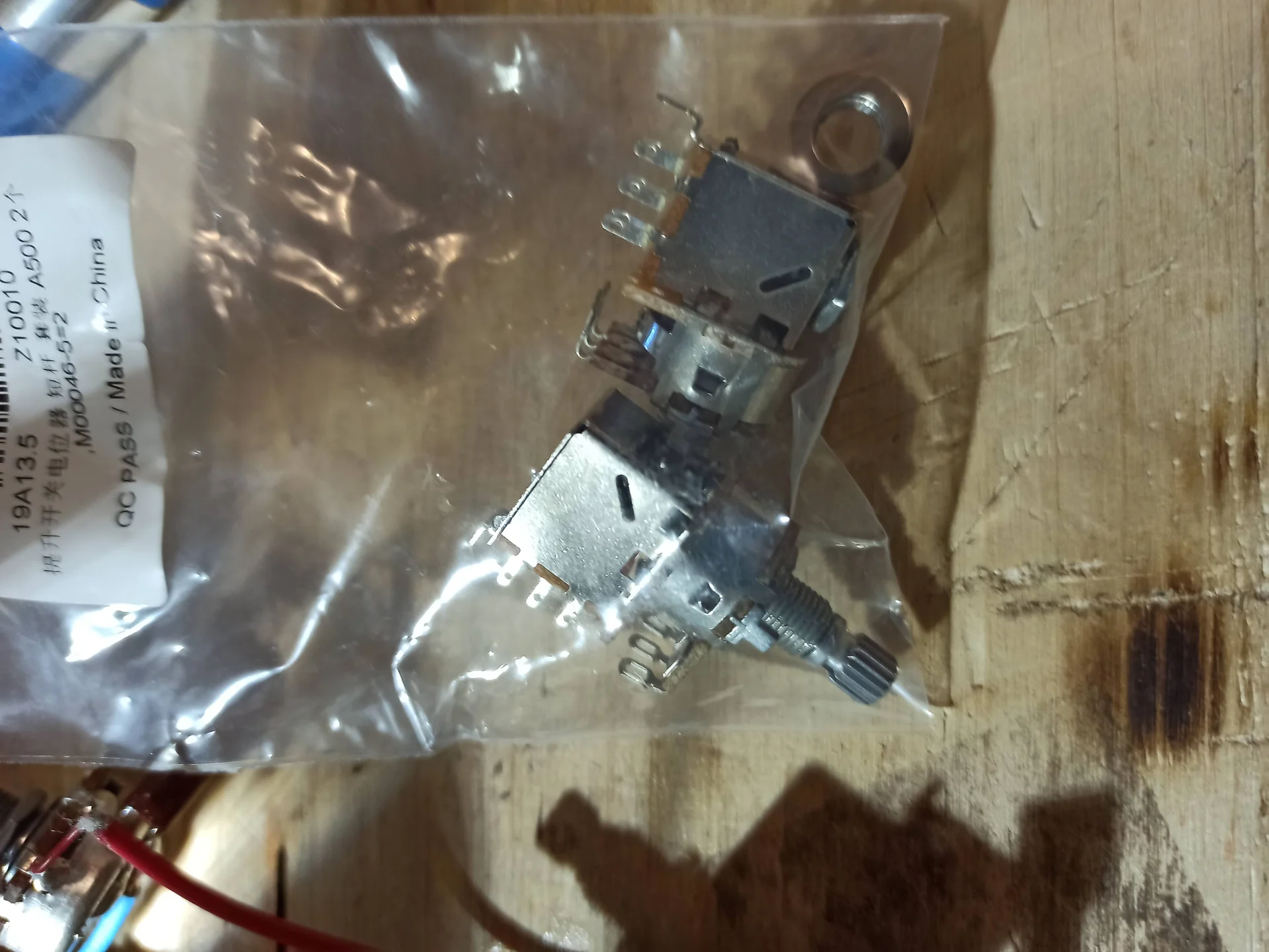
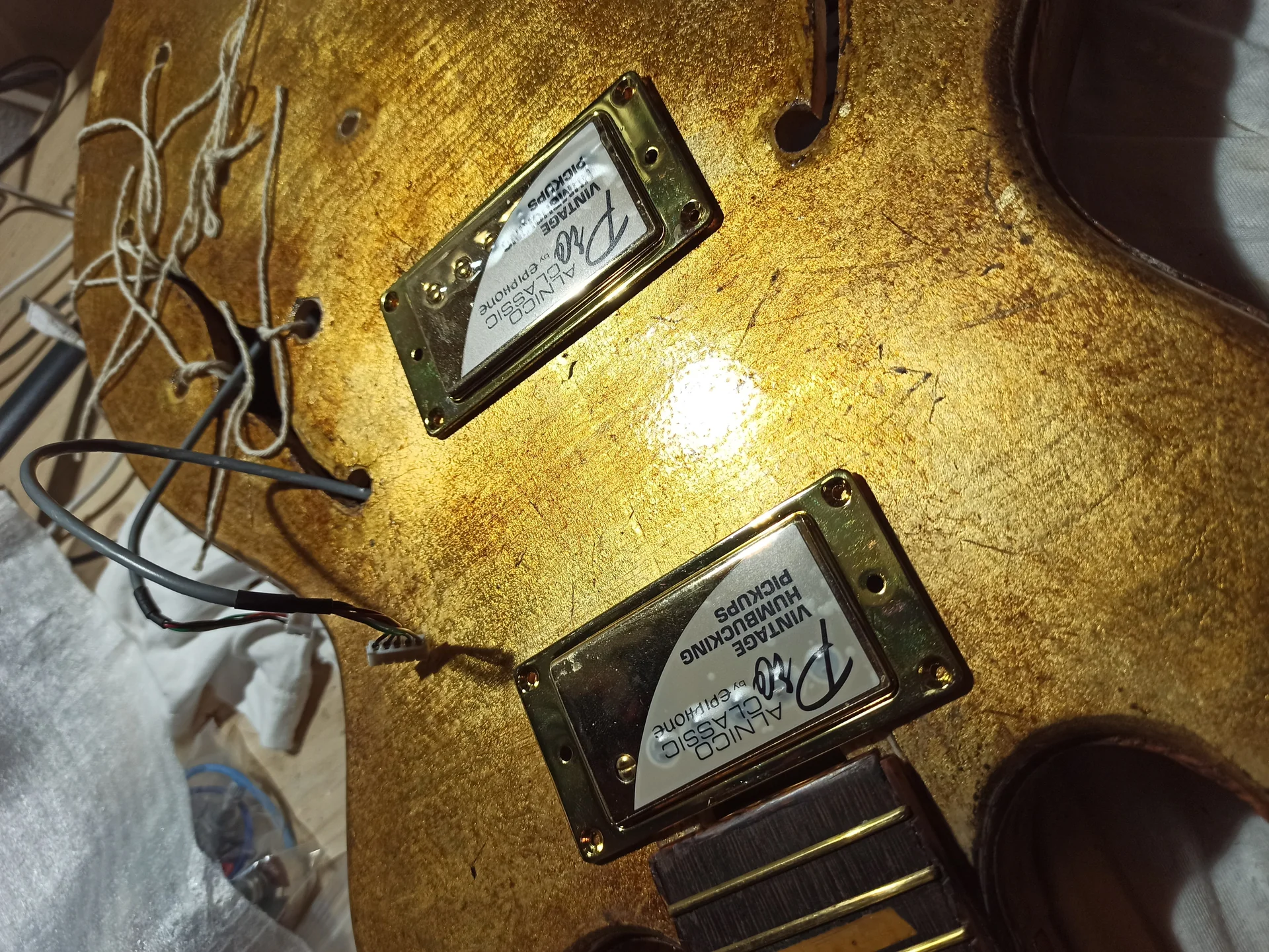
In this gallery: installation, pickups, potentiometers, es339 and wiring.
.biafax-photo-grid { display: grid !important; gap: 12px; margin: 24px 0; }
.biafax-photo-grid-3v { grid-template-columns: repeat(3, 1fr) !important; }
.biafax-photo-grid-2h { grid-template-columns: repeat(2, 1fr) !important; }
.biafax-photo-grid a { display: block; overflow: hidden; border-radius: 6px; line-height: 0; }
.biafax-photo-grid img { width: 100%; height: 100%; object-fit: cover; aspect ratio: 4 / 3; transition: transform 0.3s ease; }
.biafax-photo-grid a:hover img { transform: scale(1.03); }
.biafax-photo-grid br { display: none; }
.biafax-photo-grid-caption { text-align: center; font-style: italic; color: #555; margin: -12px 0 24px; }
.biafax-lightbox-overlay { position: fixed; inset: 0; background: rgba(0,0,0,0.92); display: flex; align-items: center; justify-content: center; z-index: 99999; cursor: zoom-out; }
.biafax-lightbox-overlay img { max-width: 92vw; max-height: 92vh; object-fit: contain; border-radius: 4px; }
@media (max-width: 768px) {
.biafax-photo-grid-3v { grid-template-columns: 1fr !important; }
.biafax-photo-grid-2h { grid-template-columns: 1fr !important; }
}
(function() {
if (window.biafaxGridLightbox) return;
window.biafaxGridLightbox = true;
document.addEventListener(‘click’, function(e) {
var a = e.target.closest(‘a[data-lightbox]’);
if (!a) return;
e.preventDefault();
var overlay = document.createElement(‘div’);
overlay.className = 'biafax-lightbox-overlay';
overlay.innerHTML = '‘‘';
document.body.appendChild(overlay);
overlay.addEventListener(‘click’, function() { overlay.remove(); });
document.addEventListener(‘keydown’, function handler(ev) {
if (ev.key === 'Escape') { overlay.remove(); document.removeEventListener('keydown', handler); }
});
});
})();
We have seen the components, but now let's try to understand more deeply the Why of certain choices. It's not just about following a pattern to the letter, but understanding the logic behind it. This will give you the freedom to experiment and customize your sound.
Impedance: Your Pickup's Load
Let's talk about impedance. Don't be scared, it's a simple concept to understand in our context. A pickup's impedance is, essentially, its "resistance" to the flow of alternating current.
Pickups and Potentiometers: Pickups have an output impedance. Potentiometers, being resistors, present an impedance to the pickup.
Optimal Pairing: To make the pickup work best and not “load” it too much, it is important to pair it with a potentiometer of adequate value.
THE single coil They have a lower impedance and are more sensitive to high frequencies. If you connect them to a 500k potentiometer, the high frequencies pass undisturbed and the sound can be too bright, almost shrill. Using a 500k pot 250k, a slight attenuation of the highs is created, which “softens” the sound and makes it more balanced.
The humbuckers They have a higher impedance and tend to produce a darker, fuller sound. If we used a 250kW pot, we would cut too many high frequencies, making the sound muddy. A 250kW pot 500k allows more highs to pass through, while maintaining clarity and articulation that would otherwise be lost.
This explains why 250kW is often recommended for single coils and 500kW for humbuckers. It's not a hard and fast rule, but it's a good starting point for a balanced sound. If you want a brighter sound with humbuckers, you can try a 1M pot. If you want a darker single coil, you can go down to 100kW (but be careful not to overdo it).
The Condenser: Cutting Frequencies with Style
We said that the capacitor, together with the tone pot, forms a low-pass filter. But why do different values produce such different results?
The Cutoff Frequency: The capacitor value determines the filter's "cutoff frequency." The higher the capacitor value (e.g., 0.047µF versus 0.022µF), the lower the frequency at which the filter begins to cut off the high frequencies.
Effect on Sound: A capacitor from .022µF will begin to cut the highs at a higher frequency, letting more upper harmonics through and producing a more open, brighter tone even when the pot is closed.
A capacitor from .047µF will begin to cut the highs at a lower frequency, eliminating more upper harmonics and producing a darker, “softer” tone when the pot is closed.
Types of Capacitors: Besides the value, the type of capacitor can also slightly influence the sound, although the impact is often a matter of debate among audiophiles.
Ceramics: Cheap and common, used on many entry-level guitars. They do the job.
Polyester (Mylar): A little more expensive, often considered to have a ’smoother“ and less ”hard“ response than ceramic ones.
Oil-Paper (PIO): Vintage and expensive. Many swear they have a warmer, more musical sound, with a smoother high-end roll-off. I tried a PIO on one of my Telecasters and I have to say the difference is noticeable, especially in the low range. It's not a revolution, but an improvement.
Orange Drop: Polypropylene capacitors, very popular for their clean sound and reliability.
Experimenting with different capacitor values and types is one of the easiest and cheapest ways to change the sound of your guitar without changing the pickups.
The Ground: Your Shield Against the Buzz
There mass, or ground, is perhaps the most underrated and yet most critical concept in guitar electronics. All components in the circuit must be connected to a common ground point. This creates a zero voltage reference and serves to:
Signal Stability: Ensures that the audio signal has a clear and stable path.
Noise Reduction: It acts as a safety net for interference. Any unwanted noise is diverted to ground, preventing it from entering the audio signal path.
A common mistake that I've made often: A faulty ground solder or a loose ground wire. The result? An infernal hum that makes you want to throw your guitar out the window. I spent entire evenings searching for a ground loop (an unwanted ground path that creates noise) on a guitar I'd hastily wired. I learned that every ground point must be solid and well connected.
Garage tip: When soldering the ground wires, try to connect them all to a single point (for example, to the back of the volume pot) and then to the jack. This helps prevent ground loops. And make sure the body shield is properly connected to the circuit's general ground.
Practical Diagrams: From Concept to Welding (Fearlessly!)
Okay, theory is important, but now let's move on to practice. There's no better way to understand how it works. electronics for guitar than to see it in action. I'll present you with three practical diagrams, starting with the simplest and working up to the most complex. Don't be intimidated by the diagrams: they're just road maps for your wires!
First, a word about the diagrams. They're not hieroglyphics. Each component has a standard symbol. The lines represent the wires. Where the lines meet, and there's a black dot, the wires are soldered together. If they cross without a dot, they're passed over each other without contact.
Basic Symbols:
Pick-up: A spiral (coil) with a magnet (broken line).
Potentiometer: A rectangle with an arrow through it (variable resistor). It has three terminals.
Capacitor: Two parallel lines (sometimes a curve) with two terminals.
Switch: A switch, designed to show the contact points.
Jack: A circle with two terminals (tip and sleeve).
Ground: A symbol with three descending lines or a downward-pointing arrow. Everything grounded goes there.
Scheme 1: The Essential Base (1 Pickup, 1 Volume)
This is the simplest schematic you can find. It's perfect for a cigar box guitar, a minimalist project, or simply to understand signal flow without too much complication.
Required Components:
1 Pickup (single coil or humbucker, it doesn't matter in this case)
1 Volume Potentiometer (e.g. A250k for single coil, A500k for humbucker)
1 1/4″ Mono Jack
Electrical wire (preferably shielded for pickup)
Tin and soldering ironHow it works:
The pickup signal goes directly to the volume pot. From there, the adjusted signal goes to the output jack. The ground of all components is connected together.
Conceptual Scheme:
“`
[Pickup] — (Hot Signal) —> [Volume Pot: Input Terminal]
|
| (Central Terminals)
Vn [Volume Pot: Output Terminal] — (Hot Signal) —> [Jack: Tip]
|
| (Ground Terminals, connected to the body of the pot)
Vn [Common Mass] —————————————–> [Jack: Sleeve]
^
|
(Pickup Ground Wire)
“`
Welding steps:
1. Pickup Mass: Take the pickup's ground wire and solder it to the body of the volume potentiometer. This is the common ground point. n2. Pickup Signal: Take the “hot” signal wire from the pickup and solder it to the input terminal of the volume pot (usually one of the outer terminals).n3. Potentiometer Mass: Solder the center lead of the potentiometer to the body of the potentiometer itself. This turns the potentiometer into a volume rheostat. No, wait. The center lead is the output. The outer lead opposite the input is ground. Let's do this: solder the center lead to the potentiometer's output lead (the other outer lead), and this wire goes to the jack. The outer lead connected to the pickup's hot signal is the input, and the other outer lead is ground. No, I messed up. Let's make it simpler:
Pot Terminals: Imagine the pot with the three terminals seen from behind: left, center, right.
Entrance: The hot wire from the pickup goes to the center terminal.
Exit: The right terminal (or left, depending on how you want the knob turned) goes to the jack's hot terminal (tip).
Mass: The left (or right) terminal is soldered to the body of the pot, which in turn is connected to ground.
Ah, here it is! I learned the hard way that the volume control terminal layout can be confusing. The most common way is: input signal on the center terminal, one outer terminal to ground, the other outer terminal is the output that goes to the jack. In this way, by rotating the knob, you vary the resistance between the input signal and the output, and simultaneously between the input and ground.
4. Output Volume: Solder the center terminal of the volume potentiometer to the “tip” terminal of jack n5. General Mass: Solder the body of the volume potentiometer to the jack's "sleeve" terminal. Make sure all ground wires are connected here.
Welding Tip: Don't rush. Heat the terminals thoroughly before applying the solder. The solder should "embrace" the metal, not form a cold ball. If the solder is cloudy and lumpy, it's a "cold solder" and won't make good contact. Do it again. It's happened to me a million times!
Scheme 2: The Classic Strat-Style (3 Single Coil, 1 Volume, 2 Tone, 5-way Switch)
This is the most iconic setup for Stratocaster-type guitars. It allows you to explore a wide range of sounds, from crystal-clear cleans to aggressive crunch. This is where the serious editing starts, eh!
Required Components:
3 Single Coils (neck, middle, bridge)
1 Volume Potentiometer (A250k)
2 Tone Potentiometers (B250k or A250k, depending on your preference)
2 Capacitors (e.g. .022µF or .047µF, often .022 for neck and .047 for center/bridge)
1 5-way switch (blade switch)
1 1/4″ Mono Jack
Electric wire, tin, soldering ironHow it works:
Each pickup has its own hot wire and ground wire. The hot wires go to the 5-way switch, which routes them to the volume pot. From the volume pot, the signal goes to the two tone pots (which affect different pickup combinations) and then to the jack. All ground wires are connected to a common ground.
Conceptual Scheme (Simplified):
“`
[Neck Pickup (Hot)] —|
[Center Pickup (Hot)] —|—> [5-Way Switch] —> [Volume Pot (A250k)]
[Bridge Pickup (Hot)] —-| |
| (Volume Output Hot Signal)
Vn ———————————
| |
V Vn [Pot Tone 1 (B250k)] ————–> [Jack: Tip]
| (with 1.022µF capacitor)
|
Vn [Pot Tone 2 (B250k)]
| (with 2.047µF capacitor)
|
Vn [Common Mass] ———————-> [Jack: Sleeve]
^
|
(All pickup grounds, pots, switches)
“`
Wiring Key Points:
5-way switch: This is the most visually complex component. It has multiple terminals. Typically, the center terminals are the outputs for the volume, while the outer terminals are the inputs for the pickups. Each pickup has a dedicated section on the switch.
Tone 1 and Tone 2: In a standard Strat, the first tone controls the neck pickup, and the second tone controls the middle pickup. The bridge pickup traditionally has no direct tone control. However, it's common to modify this scheme to have the second tone control both the middle and bridge pickups.
Tone Capacitors: Each tone pot has a capacitor connected between its center terminal and ground. This creates the low-pass filter.
Advise: When wiring your 5-way switch, use a good wiring diagram. There are various wiring options depending on the switch model and the combinations you want to achieve. Always check the datasheet for your specific switch.
Diagram 3: The Full Humbucker (2 Humbuckers, 2 Volume, 2 Tone, 3-way Switch)
This is the classic wiring harness for Les Paul-style guitars. It offers independent control for each pickup, allowing you to blend volumes and tones to create a wide range of nuances.
Required Components:
2 Humbuckers (neck and bridge)
2 Volume Potentiometers (A500k)
2 Potentiometers T