

If you are looking for a stratocaster 7 way gilmour mod Clear and practical, you're in the right place. Here you'll find the diagram, explanations of the connections, and tips for avoiding common mistakes.
Introduction: The “Why” behind the 7-Way Modification
The Stratocaster is an icon, but even icons can be improved, or at least customized. This modification, made famous by David Gilmour, is not just a whim; it is a true expansion of your guitar's sonic possibilities.
Use a mini-switch or a push-pull potentiometer to force the neck pickup in parallel with any active combination selected by the 5-way selector. This means that, in addition to the classic 5 positions, we add two more, bringing the total to 7.
The two additional combinations are what make the difference: the simultaneous activation of Neck + Bridge (a sound very reminiscent of a Telecaster) and the use of all three pickups in parallel. The latter, in particular, offers a full, rich tone with remarkable sustain, perfect for solos that need to “cut through” the mix.
It's not a question of “better” or “worse”, but about having more options at hand, expanding the versatility of your Stratocaster without distorting its soul. It's a reversible modification, which makes it even more interesting for those who, like me, love to experiment without fear of causing irreparable damage.
Key Components: The Heart of the 7-Way Modification
Before getting your hands on the soldering iron, it's essential to understand what components are involved and why they are important. It's not just about connecting wires, but about understanding the signal flow and the role of each piece.
The Standard 5-Way Selector
Your Stratocaster already has a 5-position selector that allows you to choose between the neck pickup, neck+middle, middle, middle+bridge, and bridge. This component remains the core of the primary pickup selection.
The Mini-Switch SPDT (On-On) or Push-Pull Potentiometer
This è the protagonist of our stratocaster 7 way gilmour mod. SPDT stands for “Single Pole, Double Throw” and “On-On” indicates that it has two stable positions, both active. A push-pull potentiometer performs the same function, but integrates the switch into the knob of an existing potentiometer (volume or tone), making the modification aesthetically more discreet.
- Mini-Switch: It requires drilling the pickguard, but it's sturdy and easy to operate. Personally, I prefer a mini-switch for its immediacy.
- Push-Pull Potentiometer: It does not require additional drilling, but it can be a bit more inconvenient to operate quickly during a performance. It is ideal if you want to maintain the original look of your Strat.
Its task is to “intercept” the signal from the neck pickup and, when activated, to send it to the common output point of the 5-way selector, regardless of the latter’s position. It’s a bypass, a forced “add this pickup here”.
The Single-Coil Pickups
Obviously, pickups are the sound generators. This modification works with classic Stratocaster single-coils. It does not alter their intrinsic sound, but expands their combinations, allowing you to explore new sound textures.
Potentiometers and Capacitors
These components are not directly modified by this mod, but are an integral part of the Stratocaster circuit.
- Potentiometers (Pots): They regulate the volume and tone. Generally, for single-coil, 250k Ohm (250kΩ) potentiometers are used.
- Capacitors (Caps): They are responsible for “cutting” the high frequencies when the tone knob is turned down. Typical values are 0.022µF or 0.047µF. A higher value cuts more high frequencies, making the sound darker.
Make sure they are in good condition and, if your guitar is old, consider replacing them with quality components to maximize the sound result.
Wires and Soldering
Do not underestimate the quality of cables and solders. Good quality shielded cables reduce noise, and clean and robust solders ensure a reliable connection. A "cold" solder is one of the most common causes of problems and hums.
Job Preparation: Tools and Error Prevention
Patience is your best friend when it comes to garage electronics. Don't rush and prepare everything you need.
Essential Tools
- Soldering Iron: A 25-40W one is more than enough. Clean tips are essential.
- Pond: Of good quality, preferably with flux core.
- Wire stripper: To prepare cables cleanly.
- Wire cutters: To cut off excess threads.
- Multimeter: Essential for testing continuity and identifying problems.
- Electrical cables: Thin gauge wires (22-24 AWG) for internal wiring. Different colors help avoid confusion.
- Magnifying glass: Useful for checking small solders.
- Third hand: A stand with clamps to hold components. A real lifesaver!
- Electrical tape or heat shrink tubing: To isolate connections.
- Screwdrivers: To remove the pickguard.
Pre-Soldering Tips
- Clean the Soldering Iron Tip: An oxidized tip doesn't solder well. Use a specific damp sponge or fine steel wool.
- Pre-Tin the Wires: Apply a little solder to the ends of the wires before soldering them to the components. This makes the final soldering easier and cleaner.
- Organize Your Space: Work on a clean, well-lit surface. Keep the diagram handy.
- Take Photos: Before disassembling, take several photos of the existing electronics. They will help you reassemble everything correctly if in doubt.
- Unplug the Guitar: Always, always, always disconnect the guitar from any amplifier before working on it.
Wiring Diagram: The Map of Sonic Treasure
Now that we have prepared the ground, it's time to look at the diagram. Don't be intimidated by the drawings, they are just a visual representation of where the wires go. Learning to read them is a skill that will come in handy in every guitar modification you do.
[BOX AFFILIAZIONE]
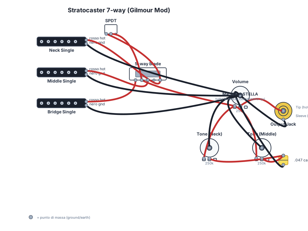
Download the diagram in SVG format and use it as a reference while soldering. Star ground is the central point: all ground wires must converge there. This is crucial for minimizing hum and ground loops, as we will see later.
In the diagram, look for the main components: the three pickups, the 5-way selector, the volume and tone potentiometers, the output jack and, of course, the mini-switch (or push-pull). The circles indicate the soldering points. Continuous lines are the “hot” wires (signal), dashed lines or ground symbols indicate the grounds.
How to Read the Diagram: Deciphering Connections Step by Step
The setup includes a standard Stratocaster circuit (3 single-coil, volume, 2 tones, 5-way selector) and an SPDT mini-toggle (On-On) or push-pull potentiometer. The secret of this stratocaster 7 way gilmour mod lies in two key connections.
The first crucial connection is soldered between the 5-way selector terminal intended for the neck pickup and the outer terminal of the mini-switch. This means that when the mini-switch is active, it “picks up” the neck pickup signal from this point.
A second wire connects the central terminal of the mini-switch to the common output of the 5-way selector (the one connected to Terminal 1 of the Master Volume). This is the point where the neck pickup signal is re-introduced into the main circuit, bypassing the normal logic of the 5-way selector.
In practice, the mini-switch acts as a switch that, when closed, sends the neck pickup signal directly to the selector's output, adding it to any pickup that is already active. If the selector is in the bridge position, with the mini-switch active you will have bridge + neck. If it is in the bridge+middle position, you will have bridge+middle+neck. Simple, right?
Soldering: Practical Steps for a Clean Job
Here's where theory meets practice. Follow these steps calmly and carefully. Remember, a good solder joint is shiny and conical, not dull and lumpy.
- Prepare the components: Check the values of potentiometers and capacitors (if you are replacing them). Cut the wires to size, strip them, and pre-tin the ends.
- Remove the pickguard: Unscrew all the pickguard screws and gently lift everything. Be careful with the pickup wires, which might be short. Do not disconnect the pickups from their grounds on the volume potentiometer, unless strictly necessary.
- Identify the soldering points: Find the 5-way selector terminal that handles the neck pickup. It is usually one of the terminals at the opposite end from the output jack. Also find the common output point of the selector, which goes to the volume potentiometer.
- Install the mini-switch (or push-pull): If you use a mini-switch, drill the pickguard in a comfortable and safe position (often between the potentiometers or near the selector). If you use a push-pull, replace one of the existing potentiometers.
- Solder the mini-switch wires:
- Solder a conductor from the 5-way selector terminal intended for the neck pickup (usually position 5, if we consider the selector from 1 to 5 starting from the bridge) to the outer terminal of the mini-switch.
- Solder a second wire from the central terminal of the mini-switch to the common output of the 5-way selector (the one connected to Terminal 1 of the Master Volume).
- Connect all grounds to the star point: This is one of the golden rules to avoid hum. All ground wires (from potentiometer casings, the back of the jack, shielding, pickups) must converge at a single point. Often, the back of the volume potentiometer is used as the star point. Make sure the guitar bridge is connected to this ground.
- Check continuity with a multimeter: Before reassembling, do a test.
- Set the multimeter to continuity mode (the one that “beeps”).
- Check continuity between the casing of each potentiometer and the output jack (sleeve). There should be continuity.
- Verify that there are no unwanted short circuits between the “hot” wires and ground.
- Test the mini-switch operation: there should be continuity between the neck pickup terminal and the selector output only when the switch is active.
- Test the instrument: Connect the guitar to an amplifier and test all selector positions, with and without the mini-switch active. Listen carefully for any hum or malfunctions.
- Adjust any hum or problems: If there is hum, review the sections on grounds. If a pickup doesn't work, recheck the relevant solders.
Troubleshooting: When Something Goes Wrong
Even the most experienced luthiers make mistakes. The key is not to get discouraged and to have a methodical approach to troubleshooting. I've spent hours in my garage chasing hum and elusive connections, and I assure you it's part of the learning process.
Tips to avoid hum: The War on Hum
Hum is every guitarist's number one enemy. Here's how to fight it:
- Avoid ground loops: If the potentiometers rest on a common metal shield (like the aluminum foil under the pickguard), do not solder ground wires between their casings. This creates a “loop” that can pick up interference. Use an open “C” or “horseshoe” path and bring each ground to the star center. The important thing is that each component is connected to ground, but that there are no multiple uncontrolled paths to the same ground. To learn more about modifications, also read the guitar modification guide.
- Star ground: I reiterate the importance of converging all grounds to a single point. This avoids potential differences that can generate noise.
- Cold welds: A solder joint that has not melted correctly can create an intermittent or high-resistance connection, generating noise. Redo suspicious solder joints.
- Shielding: Ensure that the pickup and electronics cavities are well shielded with conductive paint or copper/aluminum foil and that this shielding is properly grounded.
- Shielded cables: Use shielded cables for longer or more sensitive connections, especially the cable going to the output jack.
No Sound or Weak Sound
This is often the result of a short circuit or a signal interruption:
- Short circuit: A “hot” wire accidentally touching ground. Check every solder joint and every wire, making sure there are no unwanted contacts. The multimeter is your friend here.
- Signal interruption: A solder joint that doesn't make contact, a broken wire, a faulty component. Trace the signal path with a multimeter, starting from the pickups to the jack.
Switch Not Working
If the mini-switch doesn't change the sound or doesn't add the neck pickup:
- Check the solder joints: Make sure the two wires soldered to the mini-switch are secure and in the correct terminals.
- Switch Type: Verify that you have used an SPDT On-On switch. Other types of switches will not work correctly for this modification.
- Correct wiring: Review the diagram and make sure the wires go exactly where indicated.
Variations and Additional Considerations
There stratocaster 7 way gilmour mod is just the beginning. The world of DIY electric lutherie is full of possibilities.
Push-Pull vs. Mini-Toggle: Which to Choose?
As mentioned, the choice depends on your priorities. If you want to maintain the original aesthetic and don't mind a slightly less immediate operation, the push-pull is perfect. If practicality and activation speed are essential for you, a mini-toggle is the best solution, even if it requires drilling the pickguard. Both work the same way electrically.
Other Useful Modifications
Once you've become familiar with the soldering iron and the diagram, you might want to explore other small improvements:
- Treble Bleed Mod: Maintains high-frequency clarity when you lower the guitar's volume, preventing the sound from becoming muddy.
- Modified Tone Stacks: There are various ways to wire tone potentiometers, for example, connecting the bridge tone to the bridge pickup, or a master tone for all pickups.
- Series/Parallel Mod: For humbucker pickups, it allows switching from a series wiring (more output) to a parallel wiring (less output, brighter sound).
Every small modification is another step in understanding your guitar and its sound.
FAQ
Which potentiometers should I use?
Depends on the pickup: single-coil generally 250k Ohm for a warmer and darker sound, or 500k Ohm for a brighter and more open sound. Humbucker 500k Ohm, active 25k Ohm. For this mod, if you have single-coils, the original 250k Ohm are perfectly fine.
Can I use a different capacitor?
Yes, but the value changes the tone's cutoff frequency. Higher = darker sound (e.g., 0.047µF). Lower = brighter sound (e.g., 0.022µF or 0.015µF). Experiment to find your ideal sound.
How long does it take to install the 7-way mod?
If you already have the tools and some familiarity with soldering, it might take 1 to 3 hours. If it's your first time, allow half a day, including preparation and troubleshooting any issues.
Is it a reversible modification?
Absolutely. If you use a mini-switch and drill the pickguard, you can always replace it with a new one without holes. If you use a push-pull, simply replace it with a standard potentiometer. The original connections can be easily restored.
Is there a risk of damaging the pickups or the amplifier?
The risk is minimal if you follow the diagram and precautions. The most that can happen is a short circuit that causes the guitar not to sound or to sound bad. There are no dangerous voltages. I've made many messes in the garage and have never burned out a pickup or an amplifier with a passive modification like this.
See also
Conclusions
There Stratocaster 7 way mod Gilmour is one of those modifications that, with a minimal investment of time and money, can greatly expand the versatility of your guitar. It's not just a tribute to a great guitarist, but a practical way to add new nuances to your sonic arsenal. Remember, the key is patience, precision in soldering, and understanding each step. Don't be afraid to experiment; that's how you learn and discover new sounds.
Wiring diagrams library
No diagrams found.
Download the Luthier Survival Kit
Free PDF with checklist, problem-cause table and project card template.
 English
  Italiano
Stuck on your build?
If you ran into the same problem or have a question, drop it in the comments. I read and reply to every one.
Write a comment